SC HXs papers summary
advertisement
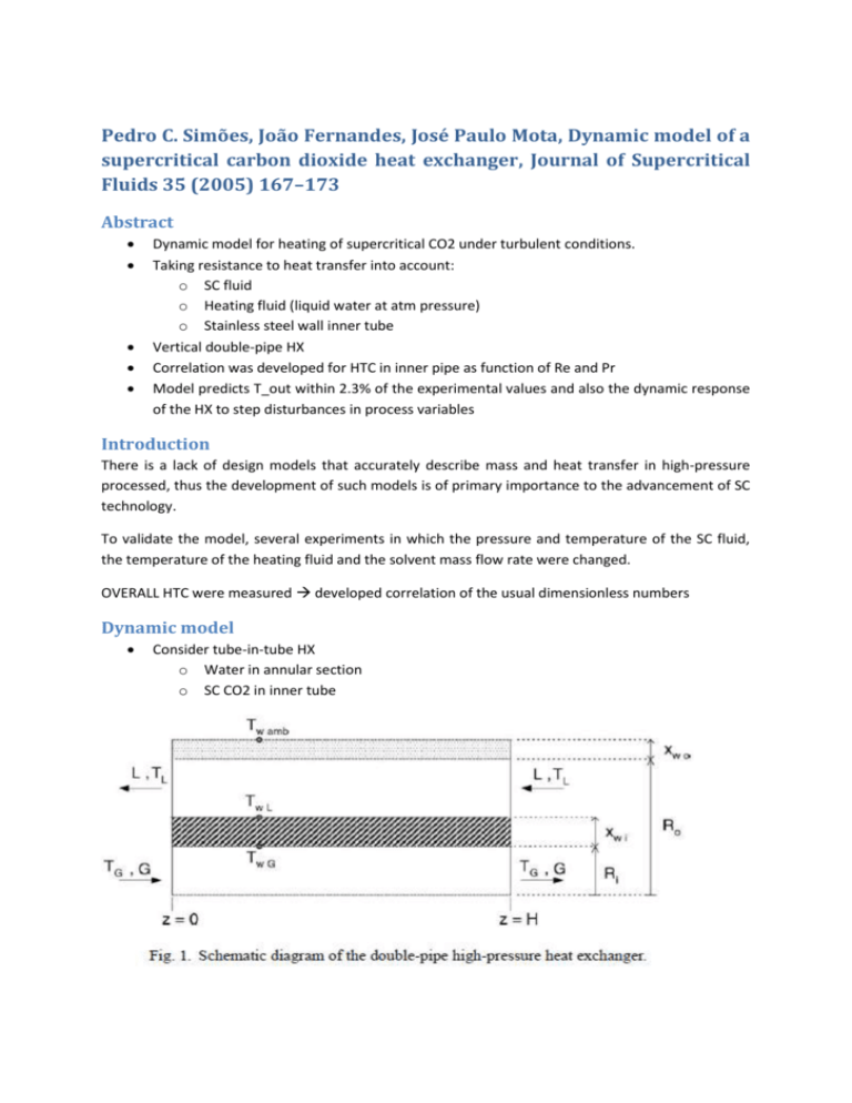
Pedro C. Simões, João Fernandes, José Paulo Mota, Dynamic model of a supercritical carbon dioxide heat exchanger, Journal of Supercritical Fluids 35 (2005) 167–173 Abstract Dynamic model for heating of supercritical CO2 under turbulent conditions. Taking resistance to heat transfer into account: o SC fluid o Heating fluid (liquid water at atm pressure) o Stainless steel wall inner tube Vertical double-pipe HX Correlation was developed for HTC in inner pipe as function of Re and Pr Model predicts T_out within 2.3% of the experimental values and also the dynamic response of the HX to step disturbances in process variables Introduction There is a lack of design models that accurately describe mass and heat transfer in high-pressure processed, thus the development of such models is of primary importance to the advancement of SC technology. To validate the model, several experiments in which the pressure and temperature of the SC fluid, the temperature of the heating fluid and the solvent mass flow rate were changed. OVERALL HTC were measured developed correlation of the usual dimensionless numbers Dynamic model Consider tube-in-tube HX o Water in annular section o SC CO2 in inner tube Assumptions o Negligible axial dispersion effects o Fully developed turbulent flow in tubes o Negligible heat losses to environment (reasonable, bcs outer tube is externally insulated) Unsteady energy balance o for the SC gas in a differential volume of the inner tube: o for the liquid in a differential volume of the annular space o o R_i = inside radius inner tube T_G and T_L = temperature of the gas and liquid phases o at the inner tube walls o h_G and h_L = gas-phase and liquid-phase HTCs o G and L= mass flow rate o _G and _L= density o C_pG and C_pL = specific heat Heat conduction equation on the inner tube wall o T_W = inner wall temperature o _W = density wall material o C_pW = specific heat wall material Boundary conditions on the inner tube : the gas and liquid temperatures Inlet boundary conditions HTC for SC-phase using a Dittus-Boelter type for forced convection inside tubes with a viscosity ratio to account for the SC radial temperature gradient HTC water side via Stein and Bagel correlation for annuli (valid for Re>4000) Numerical solution Model equations converted in system of ODEs using the control volume method o Efficient stiff-integrator for time integration To prevent non-physical oscillations of the solution convective fluxes were spatially discretized using the van Leer harmonic flux-limiter scheme implemented in the form advocated by Watersion and Deconinck Heat conduction eq. was spatially discretized using standard second-order centered finite differences. The ODE system (after spatial discretisation) was then integrated in time using the process simulation software package gPROMS. gPROMS uses the DASOLV solver which implements a backward difference formula method for the efficient solution of ODE systems. Experimental Metering pump: Model M510S, Lewa Double-pipe HX tube-in-tube counterflow Pressure gauge transducer: Model S-10, WIKA inlet section HX o Acc ± 0.25% of span Mass flow meter: Model RHM 01 GNT, Rheonik o Acc ± 0.2% of rate CO2 downward in inner tube Water upward in annulus Inner pipe AISI316 o OD = 6.35 mm o T = 1.8mm o L = 0.8m Outer tube Cu o OD = 0.05m o Insulated Temperature inlet water and CO2 calibrated resistance sensors o Acc. ± 0.10°C Pressue 10-21 MPa T_inlet, CO2 = 308-323 K Mass flow rate = 3-12 kg/h T_inlet, water = 313, 323, 333 and 343 K Mass flow rate = cte = 100kg/h MEASURED: o T_out, water o T_out, CO2 o Mass flow rate SC CO2 o Inlet pressure CO2 p neglected due to small length Results and discussion HTC CO2 Experimental heat transfer rate T_water = ± cte due to high flow rate o T_wall, out = T_bulk, water over entire length HX SC HTC averaged over entire length The SC HTC varies locally along the pipe! o But here it doesn’t deviate considerably from its local values due to the heated length and the small temperature range of the SC CO2 (T_out-T_in<10K) Variation of the experimental HTC with pressure for 2 temperatures in the inner tube wall o o All runs far from pseudo-critical region As p↑ HTC↓ o As T_wall↑ HTC↓ Influence mass flow rate CO2 o HTC↑ as mass flow rate ↑ CORRELATION o >80% of the experimental data fall within ±15% o A more accurate correlation is possible for pressure above P_crit FREE CONCETIVE FLOW o o o o Originated by density gradients due to temperature gradients as well as concentration gradients Small changes in pressure and temperature can cause non-negligible density gradients CRITERION for absence of buoyancy by Liao and Zhao for vertical tubes: For low flow rate this was not valid and the prediction over predicted the experimental data (LEFT of FIGURE) HX dynamics Predicted T_bulk, out of CO2 at steady state agree within ±2.3% of experimental data (90% within ±5%) Predicted T_bulk and T_wall of CO2 and water Comparison between experimental and simulated results for T_out as f(t) Step disturbances in process variables Step of +10K in T_inlet, water -60% CO2 mass flow and then +12K T_inlet,water Pedro C. Simões, Beatriz Afonso, João Fernandes, José P.B. Mota, Static mixers as heat exchangers in supercritical fluid extraction processes, Journal of Supercritical Fluids 43 (2008) 477–483 Abstract Comparison of performance of sc heat transfer between a Kenics static mixer and a conventional tube-in-tube HX For the same set of operating conditions the heat fluxes are ONE ORDE OF A MAGNITUDE HIGHER than the ones with tube-in-tube HXs for the same set of operating conditions HT enhancement due to the cross-sectional mixing of the fluid CORRELATION was developed Introduction A static mixer consists of a contacting device with a series of internal stationary mixing elements of specific geometry, inserted into a pipe. The added effects of momentum reversal and flow division due to the internal elements of the mixer contribute to a maximization of mixing efficiency. The benefits of dispersion efficiency, short residence times, and low flow resistance, are advantages for the use of static mixers in mass and heat-transfer applications The Kenics mixer is comprised of a series of mixing elements aligned at 90◦, each element consisting of a short helix of one and a half pipe diameters in length. Each helix has a twist of 180◦ with right-hand and left-hand elements being arranged alternatively in the pipe. The internal mixing elements direct the flow of material radially toward the pipe walls and back to the center. Additional velocity reversal and flow division results from combining alternating right- and lefthand elements, thus increasing mixing efficiency. All material is continuously and completely mixed, eliminating radial gradients in temperature in the bulk fluid. This in turn increases the thermal gradient near the hot wall and, consequently, the heat-transfer rate into the fluid. Experimental apparatus and procedure Pressure: 8-21MPa Temperatures: 288-323K Mass flow rates 2-15 kg/h Kenics static mixer: Model 37-04-065 from Chemineer Inc. o Horizontal o ID = 4.623mm o L = 178mm o 21 helical mixing elements (L/d = 1.7) Metering pump: Model M51OS, Lewa Mass flow meter: Model RHM 01 GNT, Rheonik Pressure gauge transducer: Model S-10, WIKA Differential pressure transducer: Model SMART 1151HP, Fisheer-Rosemount Depressurizing CO2 with an air-driven valve Heat supply by electrical wire, thermally insulated with flexible elastomeric rubber material T_wall_out o monitored by platinum resistance sensor o Controlled by an automatic PID regulator (ERO, electronics) drives the power dissipated by the heating tape for a CONSTANT T_wall o Additional platinum resistance sensor attached to the outer wall of the mixer for independent temperature monitoring T_in and T_out CO2 with platinum resistance sensors Steady state energy balance o Between in and out Cp obtains a maximum As T_wall, out is kept constant by PID controller the wall boundary condition = constant temperature instead of constant heat flux AVERAGE HTC SC side via Results and discussion Influence of inlet pressure and mass flow rate o HTC↑ with fluid velocity o Low p_crit highest HTC due to temperature-induced variation of the physical properties near the pseudo-critical region HTC as function of T_out o HTC max for T_bulk near pseudo-critical temperature (same trend in peak of c_p) o For higher pressure no enhancement due to higher pseudo-critical temperatures and decreased maximum peak of c_p Comparison of heat flux Q/A for Kenics and tube-in-tube (vertical downward) HXs o o Available HT area in static mixer is 15% of the area available in tube-in-tube HX Residence time of CO2 in static mixer is lower than in the tube o Same data, but corrected for the residence time o Note that τQ/Ai gives the average amount of heat released to the fluid over a residence time τ o Although the tube-in-tube heat exchanger has a smaller internal diameter than the static mixer (therefore resulting in higher superficial velocities for the same flow rate), its total length is more than four times longer than the static mixer Higher performance due to high mixing efficiency The mixer elements direct the flow of material radially toward the pipe and back to the centre. Additional velocity reversal and flow division results from combining alternating right- and left-hand elements, thus increasing mixing efficiency. Since all fluid is continuously and completely mixed, thermal gradients are eliminated in the bulk of the fluid and steepened near the hot wall. This increases significantly the wall-to-fluid heat flux. Pressure drop: influence mass flow rate o Higher pressure drop (4.3kPa) compared to straight tube (50-100Pa) doesn’t exceed 5.0 kPa and does not influence the design of the process FREE CONCETIVE FLOW or BUOYANCY o Originated by density gradients due to temperature gradients as well as concentration gradients NEAR pseudo-critical region o Small changes in pressure and temperature can cause non-negligible density gradients o CRITERION for absence of buoyancy by Liao and Zhao for horizontal tubes: o According to the results and the criterion BUOYANCY is significant BUT the criterion is not applicable for SC HT in Kenics mixers HT correlations Dittus-Boelter type for SC HT suggested by many authors : Van der Kraan suggested to use this when the temperature difference between the tube wall and bulk are small physical properties regarded constant along radial direction For higher T temperature-induced variations of physical properties + buoyancy effect (parameter ) o Here, Nubvp and Nucp are, respectively, the Nusselt numbers for buoyancy and variableproperty, and constant-property conditions. o Relative mean error : 11.6% >80% fall within ±20% Comparison between experiments and prediction
