File - need help with revision notes?
advertisement
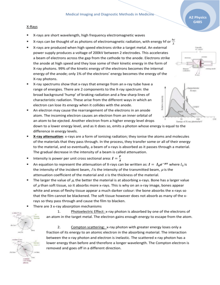
Medical Imaging and Diagnostic Methods in Medicine A2 Physics G485 X-Rays X-rays are short wavelength, high frequency electromagnetic waves X-rays can be thought of as photons of electromagnetic radiation, with energy hf or X-rays are produced when high speed electrons strike a target metal. An external power supply produces a voltage of 200kV between 2 electrodes. This accelerates a beam of electrons across the gap from the cathode to the anode. Electrons strike the anode at high speed and they lose some of their kinetic energy in the form of X-ray photons. 99% of the kinetic energy of the electrons becomes the internal energy of the anode; only 1% of the electrons’ energy becomes the energy of the X-ray photons. X-ray spectrums show that x-rays that emerge from an x-ray tube have a range of energies. There are 2 components to the X-ray spectrum: the broad background ‘hump’ of braking radiation and a few sharp lines of characteristic radiation. These arise from the different ways in which an electron can lose its energy when it collides with the anode. An electron may cause the rearrangement of the electrons in an anode atom. The incoming electron causes an electron from an inner orbital of an atom to be ejected. Another electron from a higher energy level drops down to a lower energy level, and as it does so, emits a photon whose energy is equal to the difference in energy levels. X-ray attenuation: x-rays are a form of ionising radiation; they ionise the atoms and molecules of the materials that they pass through. In the process, they transfer some or all of their energy to the material, and so eventually, a beam of x-rays is absorbed as it passes through a material. The gradual decrease in the intensity of a beam is called attenuation. ℎ𝑐 𝜆 𝑷 Intensity is power per unit cross sectional area: 𝑰 = 𝑨 An equation to represent the attenuation of X-rays can be written as: 𝑰 = 𝑰𝟎 𝒆−𝝁𝒙 where 𝐼0 is the intensity of the incident beam, I is the intensity of the transmitted beam, µ is the attenuation coefficient of the material and x is the thickness of the material. The larger the value of µ, the better the material is at absorbing x-rays. Bone has a larger value of µ than soft tissue, so it absorbs more x-rays. This is why on an x-ray image, bones appear white and areas of fleshy tissue appear a much darker colour: the bone absorbs the x-rays so that the film cannot be blackened. The soft tissue however does not absorb as many of the xrays so they pass through and cause the film to blacken. There are 3 x-ray absorption mechanisms 1. Photoelectric Effect: x-ray photon is absorbed by one of the electrons of an atom in the target metal. The electron gains enough energy to escape from the atom. 2. Compton scattering: x-ray photon with greater energy loses only a fraction of its energy to an atomic electron in the absorbing material. The interaction between the x-ray photon and electron is inelastic. The scattered x-ray photon has a lower energy than before and therefore a longer wavelength. The Compton electron is removed and goes off in a different direction. Medical Imaging and Diagnostic Methods in Medicine A2 Physics G485 3. Pair production: high energy electron passing through the electric field of the nucleus produces an electron-positron pair. Energy of the x-ray photon appears as the mass of the electron and positron. The value of µ, the attenuation coefficient, depends on the proton number of the material and the energy of the incident x-ray photon. The higher the energy of the x-ray photon, the lower the attenuation coefficient, regardless of the material. This is because the electrons will be harder to stop if they have greater speeds: more of them will simply pass straight through the material. The photoelectric effect is the method of absorption that gives the best contrast between different body materials. This is because for the photoelectric effect, µ ∝ 𝒛𝟑 . This means that for a small increase in z, there is a substantial increase in µ. Compton scattering does not help to achieve contrast because µ is independent of z. X rays are used in medicine with 2 main aims: to reduce as much as possible a patient’s exposure to harmful x-rays and to improve the contrast of the image so that tissues under investigation show up clearly in the image. Intensifier screens are used when x-ray images are recorded on a photographic film. The intensifier screens contain a phosphor – a substance that emits visible light photons when it absorbs x-ray photons. Each x-ray photon absorbed results in several thousand light photons which then blackens the film. This reduces the patient’s exposure. Image intensifiers are used when the x-ray image is being recorded digitally. Incoming x-rays strike a phosphor screen producing visible light photons. These hit the photocathode and release electrons by the photoelectric effect. Electrons are then accelerated and focussed by positively charged anode so that they strike a screen, giving out visible light. The image on this screen is viewed on a TV camera. Contrast media are swallowed or injected into the body. They are good absorbers of x-rays. They are elements with a high Z (atomic) number – like iodine and barium. This means that their atoms have many electrons with which x-rays can interact, so they are more absorbing. The main absorption mechanism for medical purposes is the photoelectric effect. Because µ ∝ z 3 , there will be a large contrast between the normal tissue and the tissue that has absorbed the barium. Computerised Axial Tomography (CAT Scans) Patient lies in a vertical ring of x-ray detectors. The x-ray tube rotates around the ring, exposing the patient to a fan shaped beam of x-rays from all direction. Detectors send electronic records to a computer and the computer software builds up a 3D image of the patient. The doctor can view ‘slices’ across the patient’s body on the screen. The limitation of conventional x-ray is that it is a 2D image. It shows bones, muscles and organs at different depths in the body superimposed on each other, making it difficult to distinguish one thing from another. Medical Imaging and Diagnostic Methods in Medicine A2 Physics G485 The CAT scan overcomes this problem because several images are taken from different angles. 3D relationships between tissues can be seen; can distinguish between tissues with similar densities; can show exact positions of tumours, allowing it to be precisely targeted with high energy x-rays or γ-rays. CAT scans do however use X-rays which is an ionising form of radiation, and one CAT scan can be equivalent to several years of background radiation. CAT scans are also expensive and can cause problems in terms of prioritising patients. Ultrasound Ultrasound is any sound wave that is above the upper limit of the human hearing range – usually above 20,000 Hz (20 kHz). In medicine, frequencies of 1-15 MHz are used. Sound waves are longitudinal; they cannot pass through a vacuum – they require a medium to travel in. The wave equation which can be used for ultrasound waves is 𝑣 = 𝑓𝜆 Ultrasound is produced by the piezoelectric effect. Transducers are used to generate and detect ultrasound. When an alternating voltage is applied across a piezoelectric crystal, the crystal will expand and contract at the same frequency as the alternative voltage. The transducer will produce ultrasound waves when the frequency of the alternating voltage equals the resonant frequency of the crystal. The ultrasound will have this same frequency. The transducer acts as a detector also: a varying stress applied to the crystal produces an induced emf which can be viewed on a CRO screen. In ultrasound scanning, ultrasound waves are directed into the body. They pass through various tissues and are partially reflected at each boundary where wave speed changes. The reflected waves are detected and used to construct an image. The amount of the incident intensity that is reflected at a boundary depends on the acoustic impedance of the two materials that the ultrasound is passing from and to. Acoustic impedance, z, is given by 𝒛 = 𝝆𝒄 where p is density of material and c is the speed of ultrasound in the medium. When ultrasound reaches the boundary between 2 materials, the greater the difference in the acoustic impedance values, the greater the fraction of incident waves that will be reflected. 𝑰 (𝒁 −𝒁 )𝟐 The fraction of incident waves reflected at a boundary is given by 𝑰𝒓 = (𝒁𝟐+𝒁𝟏)𝟐 𝟎 the graph on the right, the thickness of the bone = 𝟐 𝟏 At an air-skin boundary, 99.95% of the incident ultrasound will be reflected before it has entered the body. To overcome this, the ultrasound transducer must be coupled to the skin using a gel whose impedance value matched that of the skin. This is called impedance matching. It reduces the difference in acoustic impedance values so more of the ultrasound is transmitted rather than reflected. A scans (often used for measuring thicknesses in the body) involve a pulse of ultrasound being sent into the body. Reflected waves are detected and displayed on an oscilloscope or computer screen as a voltage-time graph. The time that a wave takes to return can be used to work out distances between structures in the body. For example, using 𝒄 𝜟𝒕 𝟐 B scans involve moving the ultrasound transducer across the area of interest. Each reflected pulse is analysed to determine the depth of the Medical Imaging and Diagnostic Methods in Medicine A2 Physics G485 reflecting surface (from the time of the echo) and the mature of the surface (from the amplitude of the reflected wave). A 2D image is built up on the screen by positioning dots to represent the positions of the reflecting surfaces. The intensity of the reflection is shown by the brightness of the dot. Doppler Ultrasound: reflected waves have a different wavelength and frequency because the object from which they are reflected is moving. If the object is moving away from the transducer, the reflected wave will have a lower frequency and longer wavelength If the object is moving towards the transducer, the reflected wave will have a higher frequency and shorter wavelength. Doppler ultrasound is used to study the speed of blood in a patient’s body. It can show the pulsating movement of blood and the heart beats. It can indicate blockages or weakening of the vessel walls, as well as faulty heart valves. Medical tracers – using radioisotopes and gamma cameras The source is prepared then injected into the patient. Time is given for the radioisotope to disperse and then the patient is exposed to a gamma camera. Caution must be taken for several hours after the procedure because the source will still be gradually leaving the body. The radioisotope source used must be a gamma emitter because alpha and beta have too short a range and are too strongly ionising so would be lethal inside the body. The source should also have a short half life. This means that λ (decay constant) is large and therefore it will give out radiation quickly so that only a small amount of the source is needed to form an image in the gamma camera. Short half life also means that any nuclide that remains in the patient will soon decay away, ensuring that they are not exposed to hazardous levels of radiation. Technetium-99m is a metastable isotope of technetium. This means that it will remain in an energetic state for some time before decaying by gamma emission. Technetium-99m is a decay product of molybdenum-99 (Mo-99) after it has undergone beta decay. In order to extract the Tc-99m form the molybdenum, a saline solution is passed through the container of Mo-99 and this dissolves out the Tc-99m. Tracers are radiopharmaceuticals – a radioisotope that has been chemically combined with other elements to produce a substance that will be taken up by the tissue of interest. The gamma camera has 4 main components: The lead collimator: gamma ray photons pass upwards through the collimator. The collimator consists of a honeycomb of cylindrical tubes which allows photons only travelling along the axis of those tubes to pass through to the scintillator. The scintillator crystal: each photon that hits the scintillator crystal produces a visible flash of light. Approximately 10% of the incident gamma ray photon energy is converted to visible light. Photomultiplier tubes: produce an electrical impulse for every photon of light that they receive. The light photon from the scintillator crystal releases a single electron from the photocathode by the photoelectric effect. The electron is accelerated to an electrode at 100V to produce 2 or 3 Medical Imaging and Diagnostic Methods in Medicine A2 Physics G485 secondary electrons. This process is repeated at each electrode to create an avalanche of electrons. These give an electrical pulse at the final electrode. Electrical signals from the photomultiplier tubes are processed electronically by a computer to produce a high quality on-screen image. Positron Emission Tomography (PET scans) The radiopharmaceuticals involved emit positrons. Fluorine-18 is a positron emitter: Once the positron has been emitted, it soon collides with an electron and the two are annihilated. Their mass is released as energy in the form of 2 gamma photons. They are emitted at 180° to each other because momentum must be conserved. These are the 2 gamma photons that are detected. Patient is injected with an isotope – a positron emitting radiopharmaceutical such as glucose tagged with fluorine-18. This tends to accumulate in tissues with high rates of respiration. Positrons are emitted and they annihilate with electrons. Pairs of gamma photons are produced and detected by ring of detectors. Using the time difference between the gamma photons arriving at the detectors we can calculate the exact position from which they were emitted. Magnetic Resonance Imaging (MRI scans) Patient lies on a bed in an external magnetic field and radiofrequency waves are sent into their body. RF waves that emerge are detected and a picture is built up. Nuclei of atoms have ‘spin’ if they have an odd number of protons and neutrons. Spin causes the nuclei to behave like tiny magnets in a magnetic field. Protons – hydrogen nuclei – are the most commonly used nucleus in medical imaging because hydrogen is present in all body tissues. When a very strong external magnetic field is applied, the protons respond by lining up in the field. A proton does not align itself directly along the external field: the magnetic axis rotates around the direction of the external field. This rotation is called precession. There are 2 possible spin states: parallel and anti-parallel. The parallel state is a lower energy; the anti-parallel state is a higher energy. The protons in the lower energy state will move to the higher energy state if they gain an amount of energy, ΔE, equal to the difference between the energies. The energy can be gained in the form of a photon. Protons precess with the same frequency regardless of their spin state. This is called the Larmor frequency and it depends on the magnetic flux Medical Imaging and Diagnostic Methods in Medicine A2 Physics G485 density of the field. The stronger the external magnetic field the faster the protons precess about it. A pulse of radiowaves is sent out by applying an alternating radiofrequency magnetic field perpendicular to the original steady magnetic field. If the frequency of the radiowaves is exactly equal to the Larmor frequency, the radiowave photons have just the right energy to be absorbed by the nuclei in the lower energy state. There is a very sharp resonance as the higher energy nuclei flip over. When the pulse of radiowaves is finished, the number of nuclei in the higher energy state decreases to what is previously was. As the protons gradually relax into their lower energy state, they release energy in the form of RF waves. These can be detected. The rate of relaxation tells us about the environment of the protons: in water and watery tissues, relaxation times are several seconds; in fatty tissue, relaxation times are several hundred milliseconds; cancerous tissues have intermediate relaxation times. This means that different tissues can be distinguished by the different rates at which they release energy after they have been forced to resonate. Components of the MRI scanner: Large superconducting magnet – produces the external magnetic field necessary to align the protons. Magnets are super-coiled to 4.2K using liquid helium. RF coils to transmit RF pulses into the body RF coils to detect the RF signal emitted by relaxing protons Gradient coils – produce an additional external magnetic field that varies across the patient’s body. The coils are arranged so that they alter the magnitude of the magnetic flux density across the length, width and depth of the body. This ensures that the Larmor frequency of the nuclei within the patient will be slightly different for each part of the body. This means that only a small volume of the body is at exactly the right value for resonance, so the computer can precisely locate the source of RF signals within the patient and construct a clear image. Computer – controls gradient coils and RF pulses; stores and analyses received data, producing and displaying images. Advantages of MRI No ionising radiation so no hazard to patients or staff Patient feels nothing during scan and no after effects MRI gives better soft tissue contrast than CAT scan Computer images generated show any section through the volume scanned or as a 3D image Disadvantages of MRI: Any metallic objects in patients like surgical pins can become heated Pacemakers affected Any metal objects in the room must be removed and room must be shielded from external radio-fields.
