network description and management
advertisement
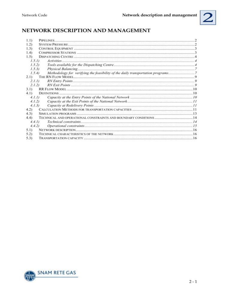
Network Code Network description and management NETWORK DESCRIPTION AND MANAGEMENT 1.1) PIPELINES ................................................................................................................................................ 2 1.2) SYSTEM PRESSURE.................................................................................................................................. 2 1.3) CONTROL EQUIPMENT ............................................................................................................................ 3 1.4) COMPRESSOR STATIONS ......................................................................................................................... 3 1.5) DISPATCHING CENTRE ............................................................................................................................ 4 1.5.1) Activities ........................................................................................................................................ 4 1.5.2) Tools available for the Dispatching Centre ................................................................................... 4 1.5.3) Physical Balancing ........................................................................................................................ 7 1.5.4) Methodology for verifying the feasibility of the daily transportation programs........................... 7 2.1) THE RN FLOW MODEL............................................................................................................................ 9 2.1.1) RN Entry Points ............................................................................................................................. 9 2.1.2) RN Exit Points ............................................................................................................................... 9 3.1) RR FLOW MODEL ................................................................................................................................. 10 4.1) DEFINITIONS ......................................................................................................................................... 10 4.1.1) Capacity at the Entry Points of the National Network ................................................................ 10 4.1.2) Capacity at the Exit Points of the National Network ................................................................... 11 4.1.3) Capacity at Redelivery Points ..................................................................................................... 11 4.2) CALCULATION METHODS FOR TRANSPORTATION CAPACITIES .............................................................. 11 4.3) SIMULATION PROGRAMS ....................................................................................................................... 13 4.4) TECHNICAL AND OPERATIONAL CONSTRAINTS AND BOUNDARY CONDITIONS ....................................... 14 4.4.1) Technical constraints................................................................................................................... 14 4.4.2) Operational constraints ............................................................................................................... 15 5.1) NETWORK DESCRIPTION ........................................................................................................................ 16 5.2) TECHNICAL CHARACTERISTICS OF THE NETWORK ................................................................................. 16 5.3) TRANSPORTATION CAPACITY ................................................................................................................ 16 2-1 Network description and management Network Code 1) GENERAL DESCRIPTION OF THE TRANSPORTATION SYSTEM Snam Rete Gas provides transportation services on its network, in accordance with the terms of its Network Code. In addition to pipelines, the network includes compressor stations, regulation, pressure reduction, gas blending and measurement plants, as well as auxiliary equipment required for gas transportation and dispatching. For invoicing and capacity booking purposes, the network is divided into a National Network (“Rete Nazionale/RN”) and a Regional Network (“Rete Regionale/RR”). The transportation service is, however, designed to be an integrated service from the RN Entry Points to the RR Redelivery Points. This chapter describes Snam Rete Gas’ network of pipelines, as at the date of the approval of the Network Code. With respect to the RN, the network cartography, published on Snam Rete Gas’ web site, also includes the networks owned by other Transportation Companies. The networks are subject to change following: a) modification to the definition of the RN by the Ministry of the Productive Activities; b) new pipelines being commissioned or existing pipelines being decommissioned; c) modification to the definition of Entry and Exit Points of the RN and of the Off-take Areas. 1.1) Pipelines The pipelines used for gas transportation have been constructed, and are managed, in accordance with the requirements contained in the Ministry Decree 24 novembre 1984, “Norme di sicurezza antincendio per il trasporto, la distribuzione, l'accumulo e l'utilizzazione del gas naturale con densità non superiore a 0,8”, together with the currently prevailing national and international technical standards and requirements. 1.2) System Pressure The Ministry Decree 24 novembre 1984 classifies the transmission and distribution pipelines in 7 categories, relating to the different maximum operating pressures. Specifically: Specie 1a 2a 3a 4a 5a 6a 7a Max exercise Pressure (rel. bar.) >24 24 P > 12 12 P > 5 5 P > 1.5 1,5 P > 0.5 0,5 P > 0.04 < 0.04 Most of the pipelines operated by Snam Rete Gas are of the first (1a), second (2a) and third (3a) categories. There are a limited number of pipelines that fall into the fourth category, and even more rare are cases of pipelines classified in the lower pressure categories (5a, 6a, 7a). The latter are typical of local distribution networks. For pipelines of categories 1a, 2a and 3a the relevant qualified authority certifies the operation of the pipeline up to a pressure level specified in the CPI (Fire Prevention 2-2 Network Code Network description and management Certificate). For the lower pressure categories, the certified pressure level is determined in relation to the specific project pressure. 1.3) Control Equipment Within the pipeline network, various types of control equipment are installed for the interconnection and the flow management of the component pipelines. This equipment is installed and maintained in accordance with the legal regulations governing operational and security requirements. In particular, the equipment includes: pressure and/or capacity regulation equipment; pressure reduction stations. In addition to the above, Snam Rete Gas’ network also contains other installations which are ancillary to gas transportation and dispatching. These are known as “punti di linea”, and include, for example, points on the network where pipeline monitoring equipment (or a PIG device) is launched and removed. Other examples of “punti di linea” include devices for pipeline sectioning and intervention (which can be manually/remotely controlled and monitored). 1.4) Compressor Stations The compressor stations located on the Snam Rete Gas network are designed to compress the gas, thereby ensuring adequate pressure for the provision of the gas transportation service across the entire pipeline system. The main components of the compressor stations are: compression units, primarily constituted of centrifugal compressors operated by gas turbines and containing their own control systems; pipelines and the associated process devices (filters, valves, air-coolers, etc); control systems for the turbo compressors and for the central process systems management; an appropriate electricity supply system; supporting infrastructure (offices, storehouses, etc). All the operational control centres are provided with the necessary systems to allow secure, remote-controlled operation. Specifically, the underlying network control systems allow the remote control and management of the gas flows by the Snam Rete Gas Dispatching Centre – described in more detail in the following section 1.5 – thereby optimising the network configuration in accordance with real time operation. The criteria adopted for the design, construction and operation of the compressor stations are based on national and international standards, as well as Snam Rete Gas’ own experience, and have been applied to obtain a high degree of security, plant engineering reliability and operational efficiency. 2-3 Network Code Network description and management 1.5) Dispatching Centre 1.5.1) Activities Snam Rete Gas guarantees the provision of its transportation service, on the basis of the Shippers’ flow programmes and through the efficient, reliable and secure use of its transportation system, including the following key activities: management and control of transportation service parameters (including those remotely measured) such as pressure, pipeline capacity and gas quality; planning and development of its core physical network assets and of the related operations; annual, monthly, weekly and daily planning of network capacity, taking into account temporary reductions of capacity due to works and/or maintenance on the network/plants; co-ordination with other national and foreign Dispatching Centres; management of emergency situations. The Dispatching Centre in San Donato Milanese controls and continuously reconfigures the gas transportation system in order to make available the required gas quantities in real time at each network point. The provision of this service relies on specialist staff in the Dispatching Centre control room working on a 24 hour per day basis. The control room contains network remote control workstations from which the operators can configure the network in response to Shippers’ nominations programs for the Gas day and to maintain the balance on the network. For this purpose, the operators utilize forecasting, optimization and simulation programs (for a detailed description of the Dispatching Centre see the following paragraph 1.5.2). The telecontrol system carries out telemetry and remote control operations. Using telemetry, relevant operational data are tracked: pressures, flows, temperatures, gas quality, compressor and valve operation . Via remote control, plant configurations can be modified to comply with operational requirements. Remote control of the compressor stations is a critical activity, managed directly by the Dispatching Centre. System monitoring is facilitated via a large-scale control panel which represents the national pipeline network. The Dispatching Centre also manages the network configuration during periods of system maintenance and emergency, utilizing advanced forecasting systems. The regional operating centre manage changes to the network pressure configuration for those parts of the network that are not remotely controlled. The regional centre oversee their own parts of the network and manage the associated control and inspection activities. 1.5.2) Tools available for the Dispatching Centre The Control Room The Dispatching Centre’s control room, which provides a 24 hour uninterrupted service, assures the network’s operation in terms of security efficiency and effectiveness. The control room contains four workstations, each having its own telephone connection, and four terminals connected to the SCADA telemetry system (Supervisory Control and Data Acquisition) – the SCADA system is integrated with optimization, forecasting and simulation systems. A fifth workstation is dedicated to 2-4 Network Code Network description and management the testing of new plant and to the periodic checking of the functioning of the telemetry system. The room contains a display panel, updated in real time with various system indicators, that represents the network configuration together with the status of key telemetered parameters The SCADA system The operators in the control room are assisted by a sophisticated system of data acquisition and telemetry (SCADA). This system collates data from the Snam Rete Gas peripheral units, and supports the real time update of the display panel and data archiving. The SCADA system allows the operators to monitor the state of the network and to apply operational adjustments. The SCADA system monitors hourly offtakes, supports the optimization of network utilization, and provides the capability, via simulation, for preventive system actions – thereby enabling system operation in a secure and efficient manner. The telecommunications system The dedicated system of telecommunications of the Dispatching Centre of Snam Rete Gas comprises a large number of peripheral stations installed on the network plants, relays, concentrators and transmission channels - connected - via radio or cable. Thousands of kilometres of fibre-optic and copper cables are located along the pipelines. In addition to supporting the telemetry and remote control systems, the telecommunications system connects the Dispatching Centre to the main operational and maintenance centres in Italy and the foreign dispatching centres. In order to maintain the highest levels of system security telephone calls made to the public telephone numbers of the peripheral maintenance centres are, during nonworking hours, automatically transferred to the Dispatching Centre Decision-support Tools CASSANDRA CASSANDRA processes the forecast for the gas redelivered to the network, valid for the next five days, based on meteorological conditions. The model includes a series of events (holidays and other events) that manage the reduced off-takes associated to them, also when significant. The model’s parameters are periodically updated based on the trends in daily quantities redelivered over the years. The applied methodology is Box-Jenkins and the models produced are of the ARIMA (AutoRegressive Integrated Moving Average) type. This forecasting approach allows the Transporter to evaluate future potential scenarios for the development of the network MELAMPO 2-5 Network Code Network description and management MELAMPO produces within-day gas forecasts using hourly volume data. The program’s calculation module is based on the statistical model of Box-Jenkins. The model’s parameters are periodically updated on the basis of the trends hourly and daily off-takes. MELAMPO uses 24 hourly models, each applicable to a specific hour of the Gas day. The model includes a series of events (holidays and other events) that manage the reduced off-takes associated to them, also when significant. The model’s parameters are periodically updated based on the trends in daily quantities redelivered over the years. The applied methodology is Box-Jenkins and the models produced are of the ARIMA (AutoRegressive Integrated Moving Average) type. The model’s forecasts, together with the hourly trends inline pack levels (and of the network pressures) allows the Dispatching Centre to take the necessary steps to keep the system in balance. Other supporting models Another two systems have been recently implemented, which process: - the hourly forecast of the demand during the Gas-day, processing the hourly modulation of the quantity redelivered during the Gas-day based on the historical series of the hourly redelivered quantities and the historical series of the temperatures; - the estimated demand for the current Gas-day and for the next five days by Off-take Area and type of users with the processing, at Off-take Area, of the total demand for the civil, industrial and thermoelectric sector; this estimate is based on the historical series of the overall daily quantities redelivered by type of use (civil, industrial and thermoelectric) for the various Off-take Ares, based on the historical series of the temperatures and on the expected temperatures. In general, the models described above include the management of the calendar of holidays in consideration of their weight based on their occurrence during the week. The applied methodology is Box-Jenkins and the models produced are of the ARIMA (AutoRegressive Integrated Moving Average) type. SSDD The optimisation system SSDD (Support System for Dispatching’s Decisions/”Sistema di Supporto alle Decisioni del Dispacciamento”) works in stable regime to meet the requirements of the transportation programmes, optimising compressor usage and minimising fuel gas consumption, using two sub systems (ARGO and OTTIMO). For each unit (turbine, compression station) the system can calculate, using regression techniques, the characteristic curves. 2-6 Network Code Network description and management Telemetered values are used to verify whether the compressors are operating within their technical limits and consuming appropriate gas quantities. SIMONE The SIMONE simulation/optimisation system runs transportation simulations in stable and dynamic regimes. It also optimises transportation in steady regime on both complex networks and individual stations. 1.5.3) Physical Balancing Snam Rete Gas, via its Dispatching Centre, controls in real time the network flow parameters (capacities and pressures) in order to guarantee the secure and efficient gas transportation from entry points to exit points - the so-called physical balancing of the system. During the Gas-day, Snam Rete Gas transports the Shippers’ gas in accordance with their transportation programmes, and assures the control, management and balancing of the network in real time. In order to achieve this, Snam Rete Gas’ Dispatching Centre has a number of tools, including: simulation and optimization systems for modelling network pressure configurations; forecasting systems that relate the volumes of off-take from the network to the prevailing meteorological conditions; remote control of network plants (distribution nodes, compression plants, regulators, etc.); remote measurement of key parameters such as pressure, capacity and temperature at significant network points. In normal operating conditions, and with balanced and accurate transportation programmes, Snam Rete Gas manages the gas flows and assures the physical balancing of the system, monitoring the pressures at relevant network points and the gas volume “stored” in the network (line-pack). Moreover, in the daily balancing regime, Snam Rete Gas provides Shippers with an hourly modulation service, as an integral part of the transportation service. This is required to manage the hourly fluctuations, principally relating to gas off-takes, that occur during the Gas-day. In order to manage the variation of the network line-pack and to provide the hourly modulation service, Snam Rete Gas acquires adequate storage capacity, in terms of both space/volume and daily peak deliverability. 1.5.4) Methodology for verifying the feasibility of the daily transportation programs The Dispatching Centre of Snam Rete Gas verifies and confirms (or otherwise), on a daily basis, the transportability of the daily programs received from Shippers for the Gas day, on the basis of their compatibility with network constraints resulting from maintenance interventions that cause interruptions/reductions to transportation 2-7 Network Code Network description and management capacity, with the availability of the compressor stations and with the network configuration prevailing on the Gas day, in particular in relation to the forecasted linepack and associated pressure levels. The technical feasibility of transportation programs is assessed using hydraulic simulations/optimisations of the network, on the basis of the planned transportation scenario and acknowledged technical standards. Generally, due to the fact that such simulations need to be completed within three hours, this verification is only performed on importation pipelines. Some general information on the verification process is provided below. The operational process Every day the Dispatching Centre receives the transportation requests from the Shippers, covering the gas quantities injected into its network at importation Entry Points, at the Entry Points from national production fields and from storage fields, as well as the off-take quantities for redelivery at the Redelivery Points. Then, the SCADA system collects the data relating to the configuration of each importation network that can be modified as a result of compressor intervention/maintenance impact The utilisation of simulation/optimisation systems allows the verification of the feasibility of the transportation programs or the identification of constraint points and development of alternative options. The result of this process is the confirmation of shippers’ transportation requests or the possible modification/reduction of the transportable quantities for the following Gas day for each Entry Point. 2) THE NATIONAL NETWORK (“RETE NAZIONALE / RN”) In this document, the definition of the term “National Network” (“RN”) corresponds to that defined in the Ministry Decree 22 December 2000 (and subsequent annual updates) - this Decree includes a comprehensive description of the Snam Rete Gas’ pipelines that are included in the RN as well as the portion of the network owned by Società Gasdotti Italia that is part of the RN and that Snam Rete Gas commercially manages. The entire national pipeline network, together with the associated installed equipment, constitutes the National Network. This includes the main importation pipelines, the national production pipelines and connections to and from storage facilities. The National Network is designed and configured to transfer bulk gas quantities from entry points to macro consumption areas. Similar objectives are served by some inter regional pipelines and even some smaller pipes which thereby also constitute part of the RN. 2-8 Network Code Network description and management The RN also includes the plants connected to the pipelines described above. 2.1) The RN Flow Model For the purposes of capacity booking (which itself is described in detail in chapter “Capacity Booking”) the Snam Rete Gas RN, and hence the Network Code itself, uses an “Entry-Exit” flow model. The Entry Points to the RN and the Exit Points from the RN are described below. 2.1.1) RN Entry Points The Entry Points defined by the RN flow model comprise: Entry Points connected to foreign importation pipelines; Entry Points relating to LNG Regassification Terminals; Entry Points from the national production fields; Virtual Entry Points from storage fields (or “hubs”). Such aggregation is used for the purpose of capacity booking and transportation programmes by the Shippers, whereas the capacity tariff is unique for the hub. For all other operational purposes, the Delivery Points on the Snam Rete Gas’ network corresponding to the connection points to the individual storage facilities are used, as defined in the specific agreements between Snam Rete Gas and the Storage Companies. 2.1.2) RN Exit Points The Exit Points defined by the RN flow model comprise: Off-take Areas, described at the following paragraph 2.1.3; Points of interconnection with exporting pipelines; Virtual Exit Points to the storage fields (“hubs”); as for the virtual Entry Points from the storage fields, this aggregation applies to capacity booking and the transportation programmes by Shippers, while the fees charged are the same for the hubs. For any operative and control objective, reference must be made to the physical points on the network, in accordance with the specific agreements reached between Snam Rete Gas and the Storage Companies. Other significant points for operational reasons are the connections between the Snam Rete Gas network and the pipelines operated by other Transportation Companies. A list of the Entry and Exit points and the relevant schematic maps are published on Snam Rete Gas website. 3) THE REGIONAL NETWORK (“RETE REGIONALE/RR”) The “Regional Network” or “RR” includes all the remaining Snam Rete Gas pipelines not included in the RN and the associated plants. The main function of the RR is to distribute gas to limited territorial (or regional) areas. 2-9 Network Code Network description and management 3.1) RR Flow Model The Regional Transportation Network is a pipeline system that covers all the national territory in Italy, and facilitates the transfer of gas from the RN Exit Points, through the Off-take Areas, to the Redelivery Points. The RR allows shippers to flow gas from Snam Rete Gas’ RN and allows the measurement and aggregation of the gas flows at downstream redelivery points. Given the high degree of complexity of the RR, it is difficult to determine a prevailing direction of gas flow. The main characteristic of the structure of the RR is that as the distance from RN increases, the pipeline diameter decreases. Each Redelivery Point is associated with a single Off-take Area. Each Redelivery Point, with the exception of exportation points and storage points during the injection phase, is considered connected to the RR. 4) METHODOLOGY FOR THE DEFINITION OF NETWORK PERFORMANCE The following sections describe network performance in normal and special conditions and the approach used to measure network performance, taking into account the existing technical and operational constraints. 4.1) Definitions Transportation capacity is the maximum gas quantity that can be injected into the system (or off-taken from the system), for the Gas day, at a specific point, respecting the technical and operational constraints fixed in each pipeline section and the maximum plants’ performances located along the pipelines. The valuation of such capacities is performed with hydraulic network simulations, carried out in appropriate transportation scenarios and respecting acknowledged technical standards. 4.1.1) Capacity at the Entry Points of the National Network The transportation capacity at the Entry Points interconnected with foreign pipelines is the maximum capacity that can be made available to Shippers for the transportation service, of firm or interruptible type. The transportation capacity at the Entry Points from national production and storage is the daily gas flow that the transportation system is capable of receiving and transporting to the Redelivery Points, on the basis of the technical verifications performed by the Transporter. Since the transportation capacity at a point is strictly dependent on the capacity of contiguous injection and off-take points, it is not possible to define a unique value of maximum flow rate that characterizes each Entry Point from national production or from storage. This is even more the case for meshed networks, that is Snam Rete Gas’s network. The values published on Snam Rete Gas’s web site are to be intended as “reference values”. For this reason, the Transporter will review an increase requested by Shippers, after a technical verification, to the transportation capacities at the Entry 2 - 10 Network Code Network description and management Points from national production or from storage, and follow the procedures of this document. 4.1.2) Capacity at the Exit Points of the National Network The transportation capacity at the Exit Points from exportation is the maximum capacity that can be made available to Shippers, for the Gas-day, for the firm transportation service. The transportation capacity at the Exit Points to storage is the daily gas flow that the transportation system is capable of receiving and transporting to these Exit Points, on the basis of the technical verifications performed by the Transporter. Since the transportation capacity at a point is strictly dependent on the capacity of contiguous injection and off-take points, it is not possible to define a unique value of maximum flow rate that characterises each Exit Point to storage. This is even more the case for meshed networks, which Snam Rete Gas’s network is. The values published on Snam Rete Gas’s website are to be intended as “reference values”. For this reason, Snam Rete Gas is willing to consider an increase, subject to technical verification, in the transportation capacities at the Exit Points to storage based on the Shippers' requests in specific points of the network, and follow the procedures of this document. The transportation exit capacity for the Off-take Areas is defined as the sum of the capacities of the Redelivery Points within each Area. 4.1.3) Capacity at Redelivery Points The transportation capacity at Redelivery Points is the daily gas flow rate which can be assured for redelivery, on the basis of technical verification. Also in this case the transportation capacity at a point is strictly related to the capacities at contiguous points. Therefore, it is not possible to define a unique value of maximum capacity that characterizes a Redelivery Point. This is even more the case for Snam Rete Gas’s meshed networks. The values published on Snam Rete Gas’s web site are to be intended as “reference values”. For this reason, upon request of increase of capacity from a Shipper, the Transporter will carry out a technical verification following the procedures foreseen in this document. For the Redelivery Points formed by the aggregation of physical interconnected points downstream of the distribution network, the published transportation capacity is the sum of the transportation capacities of each single physical point. The transportation capacity values are determined taking into account network performance, not considering the effect of REMI plants’ that are not part of Snam Rete Gas system. Therefore, it may be the case that downstream plants are not able to comply with the performance indicated for the corresponding Redelivery Point. 4.2) Calculation Methods for transportation capacities Transportation capacities at the Entry Points interconnected with foreign pipelines and at the Exit Points from exportation are determined with hydraulic simulations of transportation, using different criteria for firm and interruptible capacities. 2 - 11 Network Code Network description and management The valuation of the firm transportation capacities, the availability of which has to be guaranteed under all circumstances and at all times during the Thermal Year, in addition to normal operational constraints refers also to severe technical conditions. These conditions must include the most severe off-take conditions, that can be envisaged during the Gas year, for Shippers located on the network (special exercise conditions). The valuation of the interruptible transportation capacities, with the same operational constraints, is based on existing transportation margins with less severe technical constraints (normal exercise conditions). The transportation capacities at the Entry Points from national production are determined on the basis of a forecasted injection scenario, that derives from the capacities utilized in previous thermal years and from injection forecasts given by the operators of the production fields. The verification of such capacities is performed by hydraulic simulations that take into account the most severe off-take scenario. The transportation capacities at the Entry Points from storage and the Exit Points to storage are determined on the basis of an injection and off-take scenario forecasted on the RN. The capacities injected into/taken off from each storage are evaluated on the basis of the maximum known performance and of a severe distribution of the capacities between the storage facilities that belong to each “pool”. The verification of such capacities is performed by hydraulic simulations that take into account different possible off-take scenarios. The transportation capacity at the Redelivery Points is determined on the basis of hydraulic verifications which are based on capacity needs scenarios of the interested geographical area and which derive from available historical data and from possible contacts with Final Customers (industrials and Distribution Companies or LDC). These capacities may be updated, after a transportability technical verification, on the basis of incremental capacities requested by the Shippers, in relation to the beginning of a new Thermal Year or on a monthly basis. With respect to Redelivery Points, it must be stressed that: the capacity values published on Snam Rete Gas’s Internet web site are expressed in cubic meters/day; the network verifications, instead, take into account the “peak” flow rates expressed in cubic meters/hour. The conversion of the daily flow rates (reference and assigned) in cubic meters/hour is performed after having analyzed, for each telemetered Redelivery Point, the historical data relating to the hourly profiling of off-take, so as to determine the statistical relationship between the daily flow rate and the associated maximum hourly peak. At the Redelivery Points for which such data is not available (for example non telemetered plants), a procedure similar to that of other points belonging to the same industry sector (industrial) or belonging to the same climatic area (civil) is used; for the Redelivery Points formed by the aggregation of physical points interconnected downstream of the distribution network, the published 2 - 12 Network Code Network description and management transportation capacity is the sum of the transportation capacities of the individual physical points. This means that, when Shippers request incremental capacity, as an aggregation at a Redelivery Point, the Transporter must, for verification purposes, in addition to converting the request to the hourly peak, subdivide the request by individual physical points. 4.3) Simulation programs Gas transportation on the Transporter’s network is verified with hydraulic simulations performed using simulation systems, developed for this purpose. The simulation programs have the following characteristics: they allow the “modelling” of the network - representing it with network sections that join significant points, named “calculation points”; such points correspond to physical elements such as main connection points between the pipelines, detachment points of shunts or of distribution networks, diameter changes, significant variation of the depth profile of the pipelines. The “calculation points” are located in relation to compressor stations and of injection points in the network from importations or from the most consistent national production points; allow the derivation of: a) pressure, temperatures and gas composition in all the represented network points; b) flow rate and gas composition in each section; c) working point of turbines and compressors and calculation of the main sizes; d) determination of the operational parameters in special elements (plants, valves, importations, wells, storage facilities, off-takes); allow the concentration of the gas off-takes in the “calculation points”, as well as the gas quantities injected in the network from the Entry Points; allow the derivation of an equation system for energy, flow rate, composition balances and transportation equations consistent with formulas and models acknowledged by scientific literature and by technical gas associations; adopt a model for compressor stations based on: - the application of the control criteria characteristic of the plant for the distribution of the rate flow between the units; - realistic simulation of the working point of compressors and turbines, via a mathematic model that describes the characteristic curves of the single machines, resulting from field data (when available) or from expected curves provided by the manufacturers; such simulation allows, as an approximation, the determination of the limits of functioning of the plants based on effective limit curves (antisurge, minimum and maximum number of revolutions, maximum power); - such simulation allows, as an approximation, the determination of the limits of functioning of the plants based on effective limit curves. 2 - 13 Network description and management Network Code Further details on the simulation systems adopted by the Transporter are published on their web site, as provided for by Article 4.1 of Resolution n°137/02. 4.4) Technical and operational constraints and boundary conditions Generally, the gas quantity that may transit through a certain pipeline section in a unit of time depends not only from the maximum exercise pressure, entry and exit pressures, the diameter and length of the pipeline, the line-pack of the network, the transported gas quantities, the possible use of compression plants, but also on the offtakes and injections of gas along the section of the network and therefore the market characteristics that is supplied. The main parameters for the determination of transportation capacities can be summarized as follows: 4.4.1) Technical constraints Maximum pipelines’ exercise pressure The maximum pipelines’ exercise pressure cannot exceed the maximum project pressure, a value that normally coincides with the pressure value from CPI, that is the pressure for which the authorization is given by the competent authority (Italian Fire Department/”VVFF”). In order to avoid exceeding the pressure as provided for by the CPI – that could be caused by the depth at which the pipelines are located or by transitory transportation regimes – control and monitoring pressure systems are used, calibrated on “limit” pressure values of 1 or 2 bar less than the allowed limit (the value is determined each time taking into consideration the system’s control tolerances). In some cases maximum operational values less than those above are used on a temporary basis. Herein are listed the main values from CPI of Snam Rete Gas’s pipelines: Specie P CPI (rel. bar ) 1st 75/70/64/60 2nd 24 3rd 12 4th 5 Minimum pipelines’ exercise pressures In relation to the forecast configuration, in particular points of the transportation network minimum pressures are specified necessary to guarantee the system’s performances; as an example, the minimum entry pressure at compressor plants. In a similar way minimum pressures are considered in particular points of the network, set in relation to the minimum contractual pressure guarantee at the Redelivery Points. Performances of compressor plants For the functioning of such plants, the transportation conditions that require use of the turbo compressors limited to the maximum nominal performances are considered admissible, at which is applied a reduction coefficient. Such coefficients provide adequate security margins in order to take into consideration the level of 2 - 14 Network Code Network description and management approximation that is typical of the modeling of the functioning of the units and of adequate available performance margins. In order to guarantee the security and the reliability of the transportation system, in every plant is located at least a reserve unit that in normal operating conditions – including the most severe transportation scenarios – is able to replace each of the utilized units. This also allows the performance of the normal maintenance of the compression units without transportation interruptions or reductions. The number of spare units depends on the number and power of the compressors installed in the plant. For plants with up to three installed units there is usually one spare unit (or two units with a power less than the functioning ones, but with the sum of the corresponding powers greater than or equal to the power of each single functioning unit). In case of plants with four or more installed units, there are two spare units with a unitary power at least equivalent to that of the functioning units. Coefficients of maximum turbo compressor utilization Power generated by the turbine power Number of revolutions of the compressor and turbine 95% maximum on site 100% nominal revolutions Market scenarios These are made up of the totality of the off-takes of the Shippers of Snam Rete Gas’s transportation system. For the definition of the network’s performance, these scenarios are defined each time in order to take into account the most severe transportation conditions. As an example, for determining the capacities relating to Entry Points interconnected with the foreign pipelines, the most severe scenario for the importation from Russia and North Africa is a summer scenario, in which, as a consequence of the reduced market off-takes as a result of storage injection, the entry gas volumes must be transported for longer distances. In case of Entry Points located near important consumption centers, the seasonal nature is less accentuated. The most severe scenario may also be a winter scenario, in which pressure levels that support the supply to shunts must be guaranteed, in significant points of the network. 4.4.2) Operational constraints Delivery pressures at the Entry Points During the calculation of the capacities, the pressure is limited by the delivery contractual pressures, as indicated in paragraph 1 of chapter ”Entry and redelivery points pressure”. These pressures have been defined on the basis of a joint technical analysis performed with the operators of the interconnected foreign systems. The delivery pressures relating to the Entry Points for national production and storage are the maximum exercise pressures of the pipelines connected to such points, consistent with the Transporter’s requirement of Shippers, to deliver gas at the pipeline pressure. 2 - 15 Network Code 5) Network description and management AVAILABLE INFORMATION ON THE INTERNET WEB SITE 5.1) Network description Snam Rete Gas publishes on its website the network description as provided for by Articles 3.1 and 3.2 of Resolution n°137/02 and updates it continuously. 5.2) Technical characteristics of the network Snam Rete Gas publishes on its web site the technical characteristics of its pipeline network. In particular: length and diameter of the pipelines; maximum exercise pressure of the RN; km. of pipelines for each category, following the classification indicated in the previous paragraph 1.2. 5.3) Transportation capacity Snam Rete Gas publishes on a monthly basis on its web site, as provided for by Article 6.1 of Resolution n°137/02, the monthly updates of the transportation capacity at different points of the network. 2 - 16
