EC310 Lecture 11 - United States Naval Academy
advertisement
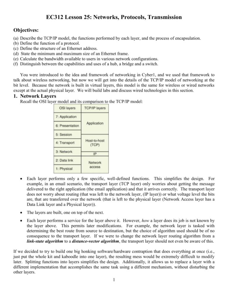
EC312 Lesson 25: Networks, Protocols, Transmission Objectives: (a) (b) (c) (d) (e) (f) Describe the TCP/IP model, the functions performed by each layer, and the process of encapsulation. Define the function of a protocol. Define the structure of an Ethernet address. State the minimum and maximum size of an Ethernet frame. Calculate the bandwidth available to users in various network configurations. Distinguish between the capabilities and uses of a hub, a bridge and a switch. You were introduced to the idea and framework of networking in Cyber1, and we used that framework to talk about wireless networking, but now we will get into the details of the TCP/IP model of networking at the bit level. Because the network is built in virtual layers, this model is the same for wireless or wired networks except at the actual physical layer. We will build labs and discuss wired technologies in this section. 1. Network Layers Recall the OSI layer model and its comparison to the TCP/IP model: Each layer performs only a few specific, well-defined functions. This simplifies the design. For example, in an email scenario, the transport layer (TCP layer) only worries about getting the message delivered to the right application (the email application) and that it arrives correctly. The transport layer does not worry about routing (that was left to the network layer, (IP layer)) or what voltage level the bits are, that are transferred over the network (that is left to the physical layer (Network Access layer has a Data Link layer and a Physical layer)). The layers are built, one on top of the next. Each layer performs a service for the layer above it. However, how a layer does its job is not known by the layer above. This permits later modifications. For example, the network layer is tasked with determining the best route from source to destination, but the choice of algorithm used should be of no consequence to the transport layer. If we were to change the network layer routing algorithm from a link-state algorithm to a distance-vector algorithm, the transport layer should not even be aware of this. If we decided to try to build one big honking software/hardware contraption that does everything at once (i.e., just put the whole kit and kaboodle into one layer), the resulting mess would be extremely difficult to modify later. Splitting functions into layers simplifies the design. Additionally, it allows us to replace a layer with a different implementation that accomplishes the same task using a different mechanism, without disturbing the other layers. 1 2. Protocols It is important to note that actual communication takes place only between the five layers in the same machine and the physical layers of adjacent machines. In the picture below, the dark black lines signify the only true transfer of data—i.e., the only real communication. Apart from the physical layer, no data are actually directly transferred from layer n on one machine to layer n on the other machine. Instead, each layer passes information/data only to the layer immediately above or below it. In a real sense, though, it seems as if the email application in the machine on the left in the picture above is communicating directly with the email application in the machine on the right. Similarly, it seems as if the transport layer on the left is communicating directly with the transport layer on the right. In fact, it seems as if each layer is on the left is communicating with its peer layer on the right. This communication is termed virtual communication. A layer in one machine communicates with the corresponding layer on the other machine using that layer's protocol. For example, the transport layer of the machine on the left communicates with the transport layer of the machine on the right using the transport layer protocol. A protocol is an agreement or a set of rules governing how a task or process should be carried out. One of the functions of the transport layer is to ensure that data is delivered without errors. The transport layers on both machines might, for example, use the Hamming code to ensure that errors are detected and corrected. In this case, the agreed upon protocol for error detection at the transport layer is the Hamming code. If the transport layer in the machine on the left is using the Hamming code to detect errors, but the machine on the right is using the CRC algorithm to detect errors, communication will not be successful. The peer entities at each layer must agree on the protocol. As another example, one of the functions of the physical layer is to determine how logical 1 and logical 0 are represented. If the physical layer of the machine on the left is representing logical one by +5 volts and logical zero as -5 volts, but the machine on the right is doing just the opposite—representing logical one as -5 volts and logical zero as +5 volts—communication will not be successful. The peer entities at each layer must agree on the protocol. 2 To recap, two machines might be connected, but if a protocol is not in place at each layer, there will be no communication. If two people are talking to (at) each other, one who only speaks English and the other who speaks only Chinese, no successful communication will occur because the two speakers are not using the same protocol (in this case, the language). If agreed upon protocols are in place, then the entities on the same layers on different machines (i.e., peer entities) carry on a conversation using the agreed-upon protocol. Some addition jargon to impress your date: Network Architecture. The set of layers and protocols is termed a network architecture. Protocol Stacks. The protocols used by a system are called the system's protocol stack. Entities at the same layer must use the same protocol, or communication will not be successful Think about how layering helps us in this scenario. We can easily replace a layer with a different implementation that accomplishes the same task using a different mechanism, without disturbing the other layers 3. Encapsulation So think again… how does a layer do its job? Here's how! At the sending end, each layer puts a header on the message received from the layer above. The header contains information necessary for the protocol to do its job. At the receiving end, each layer strips off the corresponding header and forwards the rest up to the layer above. The application layer passes its message to the transport layer. The transport layer attaches some number of bits, shown as T in the picture above and sends this onward to the network layer. The network layer then appends some number of bits, shown as N in the picture above, and so on, down the protocol stack. What actually gets transmitted across the physical layer from the source to the destination is: 3 Now, this arrives at the destination. The destination physical layer removes the bits marked P and passes the result up to the data link layer. The data link layer removed the bits marked D and uses these bits to implement the data link protocol. Then the result is passed to the network layer, which removes the bits marked N and uses these bits to implement the network layer protocol, and so forth. Example Suppose an application entity sends 1024 bytes of data and appends 96 bytes of sequencing data. This message is then sent to the data link layer where the maximum packet size is 256, 32 bytes of which are its header. How many packets will be used? How many total bytes must be transmitted? Solution: 4 4. The TCP/IP Reference Model The model we used is Section II was not chosen randomly! This model, repeated below, is termed the TCP/IP reference model. You should memorize this model! Use a mnemonic if it helps. One possibility is the West Point motto: Please Do Not Trash Army. 1. A Five Layer Model. The model we will use is the TCP/IP reference model, which consists of five layers. We list the layer, then describe some of the functions usually assigned to the layer. The application layer The application layer is concerned with general purpose facilities that involve communications: SMTP for email HTTP for accessing the web FTP for file transfer SSH and TELNET for remote log in DNS for directory assistance SNMP for network management Several other functions are also conceptually placed at the application layer: Encoding. For example: Are we using EBCDIC or ASCII? Are we using Big Endian or Little Endian? Encryption Compression Blocks of data at the application layer are termed messages. The application layer uses end-to-end protocols that do not recognize the existence of an underlying network. The notion of a networking protocol being end-to-end can be somewhat confusing, so it may be helpful to recast the notion in terms of a different network you are familiar with: the telephone network. 5 Suppose you (in Annapolis) are having a phone conversation with your friend (in Florida) over the plain-oldtelephone system. Suppose you use some acronyms in your conversation. Instead of saying, United States Naval Academy you say USNA. Instead of saying Midshipmen Regulations Manual you say MIDREGS. Instead of saying Brigade Medical Unit, you say BMU. Instead of saying Greatest Bestest Course Ehvur you say Cyber-2. Using acronyms is a form of data compression. You are conveying the exact same information to your friend, but you are doing this with fewer syllables. Now, ask yourself: Does the Phone Company—the wires, the switching stations, the fiber optic cables—care if you are using acronyms to compress your data? The answer is, of course: No. The phone company does not care, and is not even aware, of the use of compression in your voice conversation. It only matters to the end users who are actually speaking on the telephone. Now, let's switch back to computer networks. We mentioned that the application layer can implement compression. As with phones, so with computers: only the end points will care, or even be aware of the fact that data is being compressed. The underlying computer network is oblivious to this. Consider another example: Encoding. Encoding is done at the application layer, and an encoding protocol is end-to-end: the network is not aware of the encoding scheme. In a telephone conversation, the encoding scheme might be the language that you and your friend converse in. The phone company's network does not care if your conversation is in English or Spanish; this is a concern only to the end users. So, again, the application layer protocols are end-to-end. The transport layer Ideally, the transport layer is responsible for the end-to-end transfer of data from a process in the source to a process at the destination, independent of the network. Put another way, ideally the transport layer uses end-toend protocols that do not recognize the existence of an underlying network. Blocks of data at the transport layer are termed segments. Some tasks of the transport layer: End-to-end flow control End-to-end error control End-to-end congestion control 1 Multiplexing- sending several transport layer connections over a single network layer connection. The phone company analogy is useful for recognizing that the protocols at the transport layer are end-to-end. Does the phone company's network care if the person on the receiving end says: "Slow down, I'm trying to write this down" (Flow control)? Does the phone company's network care if the person on the receiving end says: "Let me read this back to you to make sure I've got it" (Error control)? The answers: No and No; these are endto-end concerns. 1 The ideal separation of layers breaks down in practice. Although congestion control algorithms are end-to-end algorithms, they are designed to alleviate congestion in a network. 6 In the next three layers, the protocols are between adjacent entities (machine-router, router-router, routermachine) The network layer The network layer is concerned with transferring data across a communications network from a source computer to a destination computer. This is the first layer that recognizes the existence of a network. Blocks of data at the network layer are termed packets or datagrams Tasks for the network layer include: Routing Internetworking-interconnecting distinct networks that use different protocols (different addressing schemes, different packet sizes, etc.) The data link layer The data link layer is concerned with transferring data across a single link connecting two nodes. Blocks of data at the data link layer are termed frames. Tasks for the data link layer include: Setting frame boundaries Error control (to make a real link into an error-free link) Link flow control (to stop a fast transmitter from drowning a slow receiver) Control access to shared channels-the Multiple Access Problem The physical layer The physical layer is concerned with sending bits over a channel: i.e., the mechanical and electrical considerations. Blocks of data at the physical layer are termed bits… so we're not really talking about blocks! See PowerPoint slide "Layers: An Illustration of Encapsulation and Decapsulation “ under Resources on the course website. 7 Example Yes sir! You caught one of your crewmembers attempting to download porn on one of your ship's computers. After putting him on report, he tells you that the computer did not seem to be working. For each of the network problems below, state which layer of the TCP/IP model the problem resides in. (a) Our computer cannot communicate with a website due to an error in the routing algorithm used by an intermediate node. (b) Our computer cannot communicate with a website because Fat Bastard spilled his Diet Coke on the cable adapter, causing a short. (c) Our computer cannot communicate with a website due to the fact that the two users (us and them) are using different end-to-end error control algorithms. (d) Our computer cannot communicate with a website because we are using the XYZ-encryption algorithm, but the website server is using the (incompatible) ABC-decryption algorithm. Solution: Example For the boxes below, fill in the names of the layers for the TCP/IP - 5 layer reference model and then place the appropriate letter in the blank associated with the layer for the proper description of its services. Layer 5 _____ Layer 4 _____ Layer 3 _____ Layer 2 _____ Layer 1 _____ a) Provides a definition of mechanical and electrical standards for communication system b) Concerned with transferring packets across a communication network c) Responsible for end to end transfer of data d) Primary function is to format and transfer files between communication message and the user’s software e) Frames of data are transferred across a single link Solution: 8 5. Ethernet A. Introduction. In the late 1960's and into the early 1970's, computers were stand-alone devices. A computer at, say, Stanford, had no way of communicating with a computer at, say, the Naval Academy. Research teams (largely funded by the DoD) began to explore methods for linking computers together, allowing them to transmit information back and forth. A breakthrough occurred when Robert Metcalfe proposed a technique for joining computers together. At heart, the computers were joined together by a wire allowing bits to flow between computers. The sketch below (from Metcalfe's 1976 conference paper) shows four computers (in red) joined together by a wire (in yellow). (Note that one of the four computers is drawn to be larger than the other three in order to show some internal details). Metcalfe, an Electrical Engineer, called his proposal "Ethernet." His company, Xerox (yes, Xerox, the same company that said "No Thank-you" to the first computer with a GUI that it had developed in-house three years before Apple, and the same company that saw no future in the first computer mouse that it had developed inhouse) was not interested in doing anything with the Ethernet proposal, so Metcalfe formed his own company in 1979 and named it 3Com. 3Com went on to sell hundreds of millions of Ethernet adapter cards as a Fortune 500 Company (3Com was purchased by HP in 2009). Network World reported that by 2010, approximately $16 billion in Ethernet equipment had been sold per year. 2 You may be wondering: Just run a wire between the computers?…there's got to be more to it than that! There are indeed four considerations. 2 First, if one computer sends data to another, there has to be a mechanism to allow the intended recipient to know where the block of data begins and ends. In other words, the recipient must be able to look at the collection of received bits—called a frame—and determine where the frame begins and ends. This is called the framing problem. Second, in order to send a frame to a specific device, every device will need a unique address. This is the address problem. Third, the receiver should be able to determine if the received frame has errors. This is called the errorcontrol problem. Fourth, we have to consider the possibility that more than one computer may place their frame on the wire at the same time. This will cause the electrical signals to collide, and both frames will be destroyed. This is called the multiple access problem. In 1996, Steve Jobs stated that "'Xerox could have owned the entire computer industry today." 9 Metcalfe's breakthrough proposal—Ethernet—handles these four issues. Other competing proposals to join computers together into a local area network (Token Ring, Token Bus, ATM, FDDI) have since fizzled and died, leaving Ethernet as the only game in town for wired local area networks. The original Ethernet transmitted at a bit rate of 10 mega-bits per second (Mbps). In 1995, a 100 Mbps Ethernet standard was introduced, dubbed Fast Ethernet. This was followed in 1998 by Gigabit Ethernet (with a data rate of 1 Gbps) and in 2002 by a 10 Gbps standard (10-Gigabit Ethernet). A 100 Gbps Ethernet standard was recently approved (2010), but commercial products have not yet reached the market. Note that we are dealing exclusively with transmitting data over a single link. Stated another way and with reference to the TCP/IP reference model: we are dealing with data link-layer concerns. Additionally, note that Ethernet is Figure implemented in a802.3 computer's 13.4 MACNetwork frame Interface Card (NIC). B. Ethernet's Solution to the Framing Problem All Ethernet variants (10 Mbps, 100 Mbps, 1 Gbps and 10 Gbps) use the same data link frame format, shown below. From, Forouzan, Data Communications and Networking, McGraw Hill, 2007 The fields are: Preamble: The preamble is not formally part of the Ethernet frame. It is added by the physical layer. It consists of the byte 10101010 repeated 7 times. The preamble allows the receiver to synchronize to the beginning of the frame. 13.7 Start Frame Delimiter (SFD): The SFD is not formally part of the Ethernet frame. It is added by the physical layer. It is the single byte: 10101011 Notice that the start frame delimiter follows the same pattern of alternating ones and zeroes as the preamble, except that it concludes with two consecutive 1's. These two consecutive 1's indicate that synchronization is over, and the real stuff is about to start: the next item will be the destination address. The Destination and the Source Ethernet Addresses: Much more on this to follow! Length or Type: This field usually specifies the kind of data the frame carries (e.g.: Is the data an IP packet?). In rare implementations, this field is used instead to serve as a Length Field, providing the number of bytes in the data field. Data and padding: This holds the data that was received from the network layer. The minimum size of the "Data and Padding" field must be 46 bytes, and the maximum size of this field is 1500 bytes. CRC: Cyclic Redundancy Code used for error detection. More on this below. 10 Example 1 What is the minimum size of an Ethernet frame? (Do not include the physical layer header in your calculation.) Solution: Example 2 What is the maximum size of an Ethernet frame? (Do not include the physical layer header in your calculation.) Solution: Example 3 Why would padding ever be used in the field marked Data and padding? Solution: So, Ethernet frames must be at least 64 bytes and are not permitted to exceed 1518 bytes. Which raises the question: Why these size limitations? The maximum Ethernet frame size is easy to appreciate. We limit the maximum frame to 1518 bytes for three reasons: To prevent a single user from hogging the network. Recall the picture on page one that shows four users sending their data over the same wire. Suppose you are one of those users, and you want to send a frame. With Ethernet, a user who wants to transmit a frame first listens on the wire to make sure no one else is already transmitting. If someone else is already transmitting, then it would make no sense for you to transmit at the same time: You would garble the transmission in progress, and your transmission would also garble. So, you patiently wait for the wire to go idle before you transmit. Since Ethernet users always politely wait for the shared wire to go idle before transmitting, a greedy user who starts transmitting could keep transmitting forever, never allowing others an opportunity to transmit their frames. To avoid this, a user is allowed to transmit at most 1518 bytes before they must stop and give other users an opportunity to transmit their frames. Error control. With Ethernet, if a single bit arrives in error, the entire frame is thrown away by the receiver. Since each bit represents an opportunity for error, the fewer bits we have, the fewer opportunities for error we have. Historical reasons. Data that arrives at the NIC must be buffered before it is sent to main memory. Although memory is very cheap today, memory was very expensive in the 1970s and 1980s when the Ethernet standard was developed. The minimum Ethernet frame size—64 bytes—is based on technical considerations that are far less intuitive. We mentioned that when a host using Ethernet wants to transmit a frame, it first listens to see if anyone else is transmitting. Only if a host senses that the medium is "quiet" does it proceed with the transmission of its frame. 11 But even if a host takes care to ensure that the medium is quiet, collisions can still occur! For example, suppose two hosts want to transmit an Ethernet frame at the same time and both first listen to ensure the medium is not in use. Both stations will detect that the medium is not in use and both will start transmitting! These sorts of collisions are unavoidable. Since collisions are unavoidable, we want to ensure that a user can tell if his transmission was involved in a collision. When Ethernet users start transmitting, they continue to listen to the channel to detect a collision. It is important for a user to know if his frame was involved in a collision since any frames involved in collisions will need to be retransmitted. Thus, we need to ensure that User-1 is still transmitting under the condition that the furthest away station (say, User-2) listens to the channel just before User-1's frame arrives, senses it idle and starts transmitting also. Based on the maximum allowed separation between users and the speed of light, it can be shown (we skip the derivation) that if the minimum frame size is set to 64 bytes (512 bits) a user will be able to tell if it was his frame that was involved in a collision. An Aside Ethernet users share access to the channel. For that reason, Ethernet is termed a Multiple Access (MA) scheme. In addition, Ethernet users listen to (i.e., sense) the channel before transmitting. This way they do not start transmitting their frame while another frame transmission from some other user is already in progress. For that reason, Ethernet is termed a Carrier Sense Multiple Access (CSMA) scheme. 3 Finally, even after an Ethernet user starts transmitting, she continues to sense the channel for collisions. Collisions can occur if two users sense the channel idle at the same time and start transmitting. When a host detects that her frame is colliding, she immediately stops transmitting (what's the point of continuing to transmit a frame if we already know it's garbled?). For this reason, Ethernet is termed a Carrier Sense Multiple Access with Collision Detection (CSMA/CD) scheme. C. Ethernet's Solution to the Address Problem Each Network Interface Card (NIC) is assigned a globally unique address—an Ethernet address—that is burned into the card's Read Only Memory (ROM). ROM is non-volatile memory whose contents cannot be altered by the user. All machines on an Ethernet LAN are guaranteed to have unique addresses. Moreover, no two hosts anywhere in the world have the same Ethernet address. So, when you buy a NIC (or, as is most often the case, a computer that contains a NIC), you are also buying a globally unique Ethernet address that only you possess. Ethernet Addresses are 6 bytes. It is important to realize that Ethernet addresses are also commonly referred to as physical addresses, hardware addresses and Medium Access Control (MAC) addresses—these terms are all synonyms! 3 Since a signal in this context is carrying our data, it is referred to as a carrier signal, when we sense the channel we are sensing to detect the presence or absence of the carrier signal. Thus, CSMA is most often called Carrier Sense Multiple Access. 12 Example 4 (a) How many bits are in an Ethernet address? (b) How many hexadecimal digits are needed to express an Ethernet address? Solution: Ethernet addresses (MAC addresses) are usually expressed in hexadecimal notation (sometimes with colons between the bytes). For example, an Ethernet address might be 06:01:03:02:2A:3D. Example 5 Two of these 48 bits in an Ethernet address are used for special purposes. Disregarding these two bits, how many possible Ethernet addresses exist? Solution: Example 6 If there are 7 billion people in the world, and we disperse Ethernet addresses uniformly, how many addresses are available for each person? Solution You should be convinced that we are in no danger of "running out" of Ethernet addresses! The uniqueness of Ethernet addresses is assured by the fact that the first 3 bytes of the address are assigned to a given manufacturer (or vendor), and this vendor must use these three bytes as the first three bytes in every NIC that the vendor manufactures. (The Institute of Electrical and Electronics Engineers—IEEE—is the group that actually does this assignment). For instance, all NICs manufactured by 3COM have Ethernet addresses starting with 02608C, all NICs manufactured by Cisco have Ethernet addresses starting with 00000C, etc. Example 7 How many possible Ethernet addresses exist for each individual vendor? Solution: Sometimes, a host may want to transmit a frame to every other user on the Ethernet LAN. A special address is reserved for this purpose. A host may send a frame to everyone by sending the frame to the broadcast address, which is the address consisting of all ones; i.e., a string of 48 consecutive 1’s. Example 8 Express the Ethernet broadcast address in hexadecimal. Solution: Referring back to the Ethernet picture on 9, any frame transmitted by any user arrives at the NIC of all other directly connected users! Stated another way, the NIC receives all frames that are sent on the wire. But it only forwards some of the frames up to the host's network layer. 13 Specifically, the NIC only forwards to the network layer: Frames addressed to its own unique address. When a frame arrives at the NIC, the NIC checks the frame to see the destination address. If the destination address of the frame matches its NIC address, then the NIC “realizes” that this data is intended for itself, and passes the frame to the network layer. If the destination address in the frame does not match its NIC address, the frame is discarded. Frames addressed to the broadcast As mentioned, a frame sent to the broadcast address (48 ones) will be accepted by every NIC. All frames if the NIC is placed in "promiscuous" mode. A vulnerability of Ethernet is the ease with which an Ethernet card can be programmed to accept all frames, even frames addressed to other users. So, any user who sets their NIC to promiscuous mode can examine the traffic sent by all other users. D. Ethernet's Solution to the Error Control Problem Recall from the picture of the Ethernet frame shown on page two that the last four bytes are used for the Cyclic Redundancy Code (CRC). The CRC is used for error detection. Ethernet can only detect errors; it cannot correct errors. If a frame arrives with errors, it is simply discarded. (Higher-layer protocols may later recognize the loss of data and take action to remedy the problem, such as by requesting retransmission. Ethernet, though, simply discards frames containing errors without giving the matter a second thought.) An Aside Ethernet's CRC algorithm hinges on a special number that mathematicians have devised. This number, given the name CRC-32, is special because it almost never divides evenly into other numbers, i.e., it almost always leaves a remainder when it is divided into another number. When the NIC crafts a frame to transmit, it fills the four byte CRC field with the specific bits that will make the total frame (including the CRC field) perfectly divisible (with no remainder) by CRC-32. When this frame is received by the destination, the destination NIC divides the received frame by CRC-32. If the frame arrives without errors, the result of the division will be zero and the frame will be accepted. If any bits were flipped en-route from source to destination the resulting division will leave a remainder and the frame will be discarded. E. Ethernet's Solution to the Multiple Access Problem We have already outlined the mechanism by which Ethernet users share a channel. They listen first before transmitting (so as not to collide with the transmissions of other users). Suppose we have 4 users on a 10 Mbps Ethernet. The 4 users share the 10 Mbps capacity of the network. If all 4 users have a lot to say, then each user will, on average, get to use the network ¼ of the time. As a rough approximation, we can say that each of the 4 users will get to send at 2.5 Mbps. From each user’s perspective, they are on a 2.5 Mbps network, not a 10 Mbps network. Make sure you are clear on why things work this way: In Ethernet, users might share a medium, and any user’s transmission will prevent all others on that same shared medium from transmitting. When one of the four users in our scenario above transmit, the other three users will be prevented from transmitting because they will first sense the channel and will not intentionally collide with another user. 14 We say that the four users in this example share a “collision domain.” If users have the ability to collide with each other, they are in the same collision domain. As a back-of-the-envelope calculation, we can say that the bandwidth 4 available to a user is given by: Figure 13.15 A network with andinwithout a domain bridge Total BW available the collision BW per user = Number of users sharing the collision domain Example 9 What is the bandwidth available to each of the users on the 10 Mbps Ethernet shown below? Solution: Example 10 Figure 1.9 A hybrid topology: a star backbone with three bus networks What is the bandwidth available to each of the users on the 10 Mbps Ethernet shown below? From, Forouzan, Data Communications and Networking, McGraw Hill, 2007 13.25 Solution: 1.12 6. Devices connecting users on an Ethernet LAN A. Hubs Ethernet first used a bus topology with heavy garden-hose size coaxial cable. In a bus topology, all users are connected in a straight-line configuration, as in Example 9 above. Later, the communication medium transitioned to unshielded twisted pair (UTP), which was ubiquitous in most office buildings. Most buildings were set up such that UTP wires terminated in a central electrical cabinet that served as a hub. Here, the term hub was simply meant as a “center of activity,” the way the term is still used as in “Denver is a hub for United Airlines.” The picture on the next page illustrates this idea. 4 In networking, the term bandwidth has two meanings. One meaning of bandwidth is data rate, measured in bits per second. That is the meaning which we use in this chapter. Later in this course (in the Wireless Module) we will encounter the other meaning of the term bandwidth. 15 Figure 1.10 An isolated LAN connecting 12 computers to a hub in a closet Electrical closet Windows Stray cup of coffee From, Forouzan, Data Communications and Networking, McGraw Hill, 2007 1.13 Now, devices called Ethernet hubs are used to connect the twisted pairs from each host together. Ethernet Hub Using the hub pictured above, we can connect four hosts together simply by plugging each host's NIC into one of the hub's four ports. When using a hub, we can consider the hosts to be, for practical purposes, electrically soldered together at the hub. Frames that arrive at one port are sent out on all other ports. A frame arriving on one port is not buffered or stored—it is simply transmitted out on all of the other ports. Fault isolation is easy with hubs—we merely have to unplug the problem host. Adding and removing hosts is also easy—we just plug in new users and unplug hosts that we want to remove from the LAN. It is important to note that a hub is a physical layer device. It only recognizes the existence of bits. When bits arrive on one port, they are sent out on all of the remaining ports. A hub does not understand that some bits that arrive are Ethernet addresses and some bits that arrive are CRC, and so forth. To a hub, everything is just bits. Example 11 Figure 15.4 A hierarchy of hubs Consider the 10 Mbps Ethernet shared by the busy users in the network below. The network uses three 5-port hubs. How much bandwidth is available to each user? From, Forouzan, Data Communications and Networking, McGraw Hill, 2007 Solution: 15.10 16 B. Separating Collision Domains with Bridges A bridge is similar to a hub in that it can be used to connect multiple hosts or multiple LANs. The distinction is that a bridge will only transmit what has to be sent to the other LAN, whereas the hub will send all information. To make this distinction clear, consider the picture below, which shows two Ethernet LANs joined together by a bridge. 1 2 3 4 5 6 9 10 11 12 13 14 Suppose Host 3 wants to send a frame to Host 5. Host 3 sends the frame out on the left LAN and it arrives at all users on that LAN, including the bridge. The bridge will inspect the frame, and see that it is destined for Host 5. The bridge knows that Host 5 is on the left LAN and must have already received the frame (since everyone on the left LAN received the frame). The important point: the bridge will not forward the frame to the rightside LAN since the bridge knows that Host 5 is not on the right-side LAN. 13.25 A bridge can be used to connect two or more Ethernet LANs like a hub, but—unlike a hub—a bridge can divide up the hosts into separate collision domains. When a frame arrives, the bridge looks at the source and destination Ethernet addresses. The bridge then decides whether the frame should be forwarded (and if so, to which outgoing port). Since a bridge looks at and understands data link addresses, it operates at the data link layer (Layer 2). A bridge is said to be a “Layer- 2 connecting device.” Hub The main advantage of bridges over hubs is improved performance. We may want to split a single heavily loaded LAN into separate LANs to improve performance by limiting collisions and forwarding only when we have to. Bridges have a few ancillary advantages. Bridges enhance reliability, since a single bad user (outputting continuously) will not disable all hosts; if bridges are used, the bad user will only kill his segment. 17 Additionally, bridges can be used to enhance security, since we can isolate portions of the network and only forward frames where they must go. Figure 13.15 A network with and without a bridge Figure Example 12 13.15 A network with and without a bridge Consider users employing 10 Mbps Ethernet. How much bandwidth does each user get in each of the three scenarios below. (a) Scenario 1: gure 13.16 Collision domains in an unbridged network and a bridged n (b) Scenario 2: (c) Scenario 3: 13.25 13.25 From, Forouzan, Data Communications and Networking, McGraw Hill, 2007 Solution: We should note that the results of the preceding calculations are, at best, approximations. We are presuming that a bridge port provides as much traffic on a LAN as a typical user. For example, in the picture above, consider the top-left collision domain. This collision domain has three users, plus the bridge port. The bridge port, however, is conveying the traffic from nine other users (the users on the other three LANs), so it may not be the case that the bridge port contributes the same amount of traffic in this collision domain as the other three users. Nevertheless, since bridges are often used to separate users who do not communicate very often, assuming a bridge port acts as a typical user often yields satisfactory results. 18 C. Switched Ethernet Look at Scenario 3 above, which shows 12 users on a 4-port bridge. What would happen if we had the 12 users on a 12-port bridge? In this case each user would be in his own collision domain (sharing it only with the bridge). An N-port bridge that serves a number of hosts N is referred to as a “Layer-2 switch" or an "L-2 switch”. Figure 13.17 Switched Ethernet Consider the scenario depicted below, which shows 7 users connected to a 9-port bridge. From here on out, whenever the number of users is less than or equal to the number of ports (as is the case here), we will use the term Layer-2 switch instead of the term bridge. From, Forouzan, Data Communications and Networking, McGraw Hill, 2007 Do collisions still occur? The answer is Yes, but only between a user and the switch. In the scenario above, all 13.27transmit at the same time since each port is now a separate collision domain. hosts can successfully Note that L-2 switches, like bridges, look at frame addresses, and operate at the data link layer. While many people use the two terms interchangeably, a switch is most often used to connect individual computers, whereas bridges usually connect LANs. Thus, in this taxonomy, with L-2 switches each computer is in its own collision domain, whereas with bridges each connected LAN forms a collision domain. Example 13 You have set up an Ethernet LAN for 10 users. For simplicity, assume the network has an efficiency of 100% and that resources are shared equally among users. How much bandwidth is available to each user if: (a) The 10 users are connected on a 10 Mbps Ethernet to a hub. (b) The 10 users are connected on a 10 Mbps switched Ethernet Solution: Example 14 You want to set up an Ethernet LAN for a group of 10 offices at the Pentagon. Each office requires 2 digital telephone lines (64 kbps each). Additionally, each office must support a peak web browsing demand of 40,000 bytes/min. (a) What is the total bit rate demand of the LAN? (b) Would a standard 10 Mbps Ethernet suffice? Solution: 19 Example 15 Match column on the left with the description on the right: Network Interface Card (a) Looks at MAC address and then forwards the frame on the correct port Hub (b) Copies incoming bits to all other ports Switch (c) Piece of equipment with a unique address that translates bits to signals and transmits the signals on the medium. Solution: Example 16 If an entire IP packet has 8096 bytes, how many Ethernet frames are required to transmit this packet? Solution: Example 17 Answer True or False to the following statements: (a) An Ethernet address is normally expressed in decimal. (b) An Ethernet address is burned into hardware and never changes (c) An Ethernet address is used at the network layer to address packets. (d) An Ethernet address, MAC address, and Hardware address are all the same thing. (e) When I log on to different networks my Ethernet Address can change every time. Solution: 20 An Aside Fast Ethernet (1995) Fast Ethernet uses the same frame format as “standard Ethernet”, i.e., it still uses 48-bit data link addresses and uses the same frame fields as shown on page 2 of these notes. Fast Ethernet is backward-compatible with standard Ethernet. And, perhaps surprisingly, it uses the same minimum and maximum frame lengths as standard Ethernet. Also, it has the same maximum physical length as standard Ethernet (100 meters for UTP). There is a big difference: Fast Ethernet operates at 100 Mbps. So…how do we raise the data rate? The details are rather technical, and have to do with the improvements in technology over the years. The original Ethernet operates at 10 Mbps, but required a special type of signaling called Manchester encoding. Advances in transmission media allowed for a signaling scheme that supported higher data rates. Better clock circuitry allowed us to raise the transmission speed without worrying about loss of synchronization. Instead of using one twisted pair, we use four twisted pairs: 1 to the switch, 1 from the switch, and 2 that are switchable to support the current direction of traffic flow. TWISTED PAIR 1:Always to the network TWISTED PAIR 2:Always from the network TWISTED PAIR 3 and TWISTED PAIR 4 Can be switched from one direction to the other, to support the current desired direction of traffic flow Finally, 3-level signaling is used at the physical layer. Instead of sending a 0 or 1, we can send 0, -1 or +1. Assistant Professor Patrick Vincent and LCDR Jesse Atwood 21
