ESM methods
advertisement
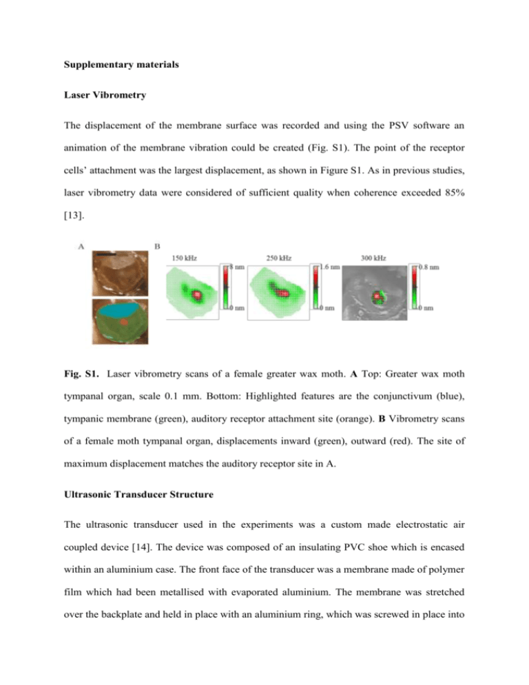
Supplementary materials Laser Vibrometry The displacement of the membrane surface was recorded and using the PSV software an animation of the membrane vibration could be created (Fig. S1). The point of the receptor cells’ attachment was the largest displacement, as shown in Figure S1. As in previous studies, laser vibrometry data were considered of sufficient quality when coherence exceeded 85% [13]. Fig. S1. Laser vibrometry scans of a female greater wax moth. A Top: Greater wax moth tympanal organ, scale 0.1 mm. Bottom: Highlighted features are the conjunctivum (blue), tympanic membrane (green), auditory receptor attachment site (orange). B Vibrometry scans of a female moth tympanal organ, displacements inward (green), outward (red). The site of maximum displacement matches the auditory receptor site in A. Ultrasonic Transducer Structure The ultrasonic transducer used in the experiments was a custom made electrostatic air coupled device [14]. The device was composed of an insulating PVC shoe which is encased within an aluminium case. The front face of the transducer was a membrane made of polymer film which had been metallised with evaporated aluminium. The membrane was stretched over the backplate and held in place with an aluminium ring, which was screwed in place into the aluminium case. This ring provided electrical connection between the case and the metallised front face of the membrane. Powering the Transducer The transducer electronic system is shown in Figure S2. The transducer was powered with a high voltage power supply (475R photomultiplier power supply, Brandenburg, Dudley, UK), which provided a bias voltage. The sound signal was created using different function generators; for the electrophysiology experiments where sound pulses were created (Arbitrary Waveform generator, TGA12102, TTi), and for the laser vibrometry experiments where a pure tone sine wave was used (Tektronix, Dual Channel-AFG 3102). Fig. S2. The equipment used to power the transducer. Transducer Power Output The output of the transducer was measured with a microphone and preamplifier (Bruel and Kjæl, Microphone: 4138, Preamplifier: Nexus 2690). The transducer was powered as previously described, with the function generator output set at 5 Vpp and 10 Vpp (pp: peak to peak). The sound pressure level was measured with the microphone 10 cm away from the transducer. The output of the microphone was measured on an oscilloscope (Tektronix, DPO 2014), and this was recorded for frequencies between 50-120 kHz at 10 kHz intervals (see Fig. S3). The transducer output is measured from 100-300 kHz [14], providing a known sound stimulus at all frequencies tested. 110 5 Vpp 10 Vpp Sound Level (dB) 100 90 80 70 60 50 60 70 80 90 Frequency (kHz) 100 110 120 Fig. S3. The sound level output of the transducer at two different driving voltage levels, 5 Vpp and 10 Vpp. The sound level (dB SPL) was recorded using a microphone, between 50120 kHz, in steps of 10 kHz. The electrophysiology experiments’ sound stimuli, 20 ms sound pulses, were investigated to rule out the possibility that there were other (lower) frequencies being created due to artefacts. To test this two transducers were used, one to emit the sound and one to detect it, as the frequencies tested were too high to use the microphone. The detected sound pulses were recorded on an oscilloscope (Tektronix, DPO 2014). The recorded sound pulses clearly demonstrate a correct signal at all frequencies investigated, indicating that no extra frequencies were being produced (see Fig. S4). A FFT of the recorded sound pulses confirmed that no other frequencies were present. Fig. S4. Start of a sound pulse used in moth electrophysiology experiments, recorded using a second transducer. The sine wave recorded was as expected, and so no extra frequencies were being created. This was the same for the range of frequencies tested. The above example is a 200 kHz sound pulse. Simultaneous Laser and Electrophysiology Experiments To ensure the simultaneity of mechanical and neural sensitivity, a combined experiment measured the mechanical motion of the tympanum and the electrophysiological response whilst the ear was stimulated with ultrasound pulses. The moth was prepared as for electrophysiology experiments; the laser vibrometer was then positioned to record the membrane displacement. As the sampling rate was 1.024 MHz over a period of 512 ms, the oscilloscope could not be used for these experiments due to lack of memory space, and so the laser vibrometer acquisition system was used to record the data instead. The sound pulses produced by the function generator and the electrophysiology voltage signal were combined with a custom-built summing amplifier and recorded using the laser vibrometer reference channel. The laser vibrometer voltage signal of the membrane displacements was also recorded through the second channel. The recorded data set of the combined sound and electrophysiology data was analysed with LabVIEW, as the two signals occupy different frequency bands they were separated using bandpass filters (Bessel, 16th Order). Further filtering was done of all the signals using the LabVIEW program to remove noise. The sound stimulus was produced as was previously described for electrophysiology experiments, a range of frequencies were used and a high sound level of 100 dB SPL was used so that the response of the hearing organ would be easily detectable on both the laser vibrometry recordings and electrophysiology. These time-domain recordings clearly show the onset of tympanal motion followed by a volley of neural spikes (Fig. S5). Fig. S5. Simultaneous recording of the mechanical and neural auditory response of a greater wax moth. The top trace is the electrophysiological response with the sound pulses highlighted in green. The lower trace is the averaged response to 5 sound pulses. Sound stimulus, 200 kHz (green) elicits a mechanical motion (red). Neural activity (black trace) appears after some latency. References 13. Windmill J. F. C., Göpfert M. C. & Robert D. 2005 Tympanal travelling waves in migratory locusts. J. Exp. Biol. 208, 157-168. 14. Whiteley S. M., Waters D. A., Hayward G., Pierce S. G. & Farr I. 2010 Wireless recording of the calls of Rousettus aegyptiacus and their reproduction using electrostatic transducers. Bioinspir. Biomim. 5, 026001.


