Scanning Technique - Machine Settings
advertisement
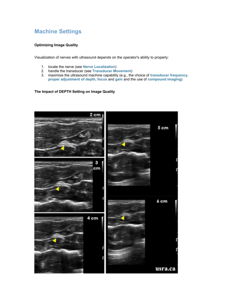
Machine Settings Optimizing Image Quality Visualization of nerves with ultrasound depends on the operator's ability to properly: 1. 2. 3. locate the nerve (see Nerve Localization) handle the transducer (see Transducer Movement) maximize the ultrasound machine capability (e.g., the choice of transducer frequency, proper adjustment of depth, focus and gain and the use of compound imaging) The Impact of DEPTH Setting on Image Quality The figures above illustrate how the image of the median nerve in the forearm (arrowhead) gets smaller and smaller as the depth is increased from 2-6 cm. It is important to select the appropriate depth setting (e.g. 2 cm in this case) according to the target nerve location. The Impact of GAIN Setting on Image Quality The GAIN function compensates for attenuation (a reduction in sound amplitude) as sound travels deep into the body. The intensity of the returning signals can be amplified by the receiver upon arrival so that the displayed image is brighter and more visible on the screen. Gain can be adjusted for the near field, far field or the entire field (overall gain). Excessive increase in GAIN will add "noise" to the image. An Illustration of Different Gain Settings Figure A shows a proper gain settings. Figure B shows under gain thus the overall image is very dark. The muscle layers are not well visualized. Figure C shows excessive gain thus the overal image is very bright. The Impact of FOCUS Setting on Image Quality Image quality and beam focus is best at the focal zone. Most modern electronically steered transducers provide electronic focusing adjustable for depth. It is important to place the FOCUS at or slightly below the level of the target structure of interest. Infraclavicular Region (8-12 MHz Range) Figure A shows inappropriate focus setting at a superficial level (< 2 cm) resulting in a dark image. The target structures (AA = axillary vessels and Arrowheads = cords) are 5-6 cm deep to the skin. Figure B shows appropriate focus setting at 5-6 cm. The target structures (AA = axillary vessels and Arrowheads = cords) are 5-6 cm deep to the skin. The Impact of COMPOUND IMAGING on Image Quality COMPOUND IMAGING is a broad bandwidth technology that combines multiple coplanar images captured from different beam angles and from multiple ultrasound frequency spectra to form a single image in real time. Spatial compounding reduces speckle artifacts and improves contrast resolution. No Compound Imaging Compound Imaging Median Nerve in the Forearm (12 MHz Transducer, 3 cm Depth) No Compound Imaging Compound Imaging Supraclavicular Region (10 MHz Transducer, 3 cm Depth) No Cross Beam (No Compound Imaging) Cross Beam (Compound Imaging) Color Doppler Color Doppler is an instrument to characterize blood flow. The Doppler effect occurs when there is a moving source (blood flow of red blood cells, RBC) and a stationary listener (ultrasound transducer). There is an apparent change in the returning echoes due to the relative motion between the sound source and the receiver. If the source (RBC) is moving towards the receiver (transducer), the perceived frequency is HIGHER (display in RED) and when the source (RBC) is moving away from the receiver, the perceived frequency is LOWER than the actual (display in BLUE) It is important to note that Color Doppler detection of flow and flow direction is worst when the transducer is perpendicular (90 degrees) to the vessel and best when the transducer is parallel (0 degrees) to the blood flow. Transducer perpendicula r to radial artery (no flow is detected) Transducer aiming away from artery (flow in BLUE) Transducer aiming towards artery (flow in RED) For ultrasound guided regional anesthesia, Color Power Doppler (CPD) is useful for differentiating vascular from non vascular structures. CPD is more sensitive than Color Doppler in flow detection but does not indicate flow direction. Transducer perpendicula r to radial artery (weak flow is detected) Transducer aiming towards or away from artery (strong flow is detected) Retrieved on 12-10-2010 from www.usra.ca


