Supplementary Figure 1
Supplementary Figure 1
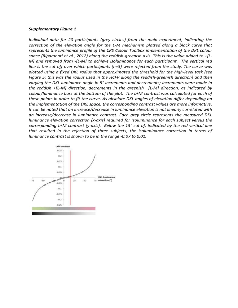
Individual data for 20 participants (grey circles) from the main experiment, indicating the correction of the elevation angle for the L-M mechanism plotted along a black curve that represents the luminance profile of the CRS Colour Toolbox implementation of the DKL colour space (Ripamonti et al., 2012) along the reddish-greenish axis. This is the value added to +[L-
M] and removed from -[L-M] to achieve isoluminance for each participant. The vertical red line is the cut off over which participants (n=3) were rejected from the study. The curve was plotted using a fixed DKL radius that approximated the threshold for the high-level task (see
Figure 5; this was the radius used in the HCFP along the reddish-greenish direction) and then varying the DKL luminance angle in 5° increments and decrements; increments were made in the reddish +[L-M] direction, decrements in the greenish –[L-M] direction, as indicated by colour/luminance bars at the bottom of the plot. The L+M contrast was calculated for each of these points in order to fit the curve. As absolute DKL angles of elevation differ depending on the implementation of the DKL space, the corresponding contrast values are more informative.
It can be noted that an increase/decrease in luminance elevation is not linearly correlated with an increase/decrease in luminance contrast. Each grey circle represents the measured DKL luminance elevation correction (x-axis) required for isoluminance for each subject versus the corresponding L+M contrast (y-axis). Below the 15° cut of, indicated by the red vertical line that resulted in the rejection of three subjects, the isoluminance correction in terms of luminance contrast is shown to be in the range -0.07 to 0.01.
