SOM_Chen_Revised
advertisement

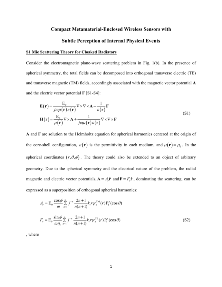
Compact Metamaterial-Enclosed Wireless Sensors with Subtle Perception of Internal Physical Events S1 Mie Scattering Theory for Cloaked Radiators Consider the electromagnetic plane-wave scattering problem in Fig. 1(b). In the presence of spherical symmetry, the total fields can be decomposed into orthogonal transverse electric (TE) and transverse magnetic (TM) fields, accordingly associated with the magnetic vector potential A and the electric vector potential F [S1-S4]: E r E0 1 A F j r r r E 1 H r 0 A + F r j r r (S1) A and F are solution to the Helmholtz equation for spherical harmonics centered at the origin of the core-shell configuration, r is the permittivity in each medium, and r 0 . In the spherical coordinates r, , . The theory could also be extended to an object of arbitrary geometry. Due to the spherical symmetry and the electrical nature of the problem, the radial magnetic and electric vector potentials, A = Ar rˆ and F = Fr rˆ , dominating the scattering, can be expressed as a superposition of orthogonal spherical harmonics: Ar E 0 Fr E 0 cos sin i n j n 1 n j n 1 2n 1 ki r nTM (r ) P1n (cos ) n(n 1) 2n 1 ki r nTE (r ) P1n (cos ) n(n 1) , where 1 (S2) anTM jn k1r bnTM hn(2) k1r if nTM (r ) d nTM jn kc r enTM yn kc r if TM (2) if jn k0 r cn hn k0 r anTE jn k1r nTE (r ) d nTE jn kc r enTE yn kc r TE TE (2) jn k0 r cn hn k0 r 0r a a r ac (S3) r ac if 0r a if a r ac if r ac (S4) and ki 0 i and i 0 / i are the wave number and characteristic impedance of each medium, jn and yn are the spherical Bessel functions of the first and second kind of order (2) n , and hn is the spherical Hankel function of the second kind of order n. For the mantle cloaking case in Fig. 1(c), the racial function is written as: anTM jn k1r bnTM hn(2) k1r if 0 r ac (r ) TM (2) if r ac jn k0 r cn hn k0 r (S5) TE TE (2) an jn k1r bn hn k1r if 0 r ac (r ) TE (2) if r ac jn k0 r cn hn k0 r (S6) TM n TE n The scattered fields may now be expanded into multipole fields with scattering coefficients cnTM and cnTE of order n. As the dipolar radiation can be described as TM1 wave, the coefficient d nTM describing fields re-radiated by a small dipole [S4], which is correlated to the coefficient describing the local field, anTM , as: d1TM n a1TM , where n j1n k03 / 61 1 anTM , is the electric polarizability of the dipole antenna with its expression described in the main text, and nm is the Kronecker’s delta function. We note that the electric dipole TM1 harmonic is the only nonzero scattering contribution from the loaded dipole, i.e. d nTM 0 for n 1, since j1 () 1 and jn () 0 for n 1. By enforcing the proper continuity of the tangential electric and magnetic fields at the 2 interfaces r a and r ac , the scattering coefficients can be compactly written as: TM n c U nTM U nTE TE TM , cn TE , U n jVnTM U n jVnTE (S7) For the cloak cloaking case [Fig. 1(b)], U nTM , VnTM , U nTE and VnTE are given by jn k1a n h1(2) k1a U TM n TM n V jn kc a yn k c a 0 k2 a jn kc a c k2 a yn kc a c 0 jn kc ac yn kc ac jn k0 ac 0 k2 ac jn kc ac c k2 ac yn kc ac c k2 ac jn k0 ac 0 jn k1a n h1(2) k1a jn kc a yn k c a 0 k2 a jn kc a 2 k2 a yn kc a c 0 jn kc ac yn kc ac yn k0 ac k2 ac jn kc ac 2 k2 ac yn kc ac c k2 ac y n k0 ac 0 (2) k1a jn k1a n k1a hn k1a 1 0 (2) k1a jn k1a n k1a hn k1a 1 0 0 , , (S8) where the wavenumbers in different regions are described by the respective constitutive parameters as k1 10 , kc c 0 , and k0 0 0 . The scattering coefficients cn can be similarly TE obtained by electromagnetic duality, but setting n 0. For the mantle cloaking case [Fig. 1(c)], we assume that a patterned metallic surface composed of subwavelength periodic structures may be modeled as an isotropic and homogenous averaged surface impedance Z s RS iX S , relating the averaged tangential electric field at the surface E tan to the averaged induced surface current J s as: Etan Z s J s , where J s rˆ H tan H tan is induced by the discontinuity of tangential magnetic fields at the surface. Consider the geometry in the inset of Fig. 4(d), the expressions of the scattering coefficients for a dipole antenna embedded 3 in the concentric, multilayered spherical structure (i.e. dielectric core, cladding layer and mantle cloak) are given in the similar notation of (S8) by: U nTM jn k1a n h1(2) k1a jn k 2 a yn k 2 a 0 (2) k1a jn k1a n k1a hn k1a 1 k 2 a jn k 2 a 2 k 2 a yn k 2a 2 0 0 jn k2 ac k2 ac jn k2 ac j 2 ac Z s yn k 2 ac k 2 ac yn k 2 ac j 2 ac Z s jn k 0ac 0 k2 ac jn k2 ac 2 k2 ac yn k2 ac 2 k2 ac jn k0 ac 0 jn k1a n h1(2) k1a jn k 2 a yn k 2 a 0 (2) k1a jn k1a n k1a hn k1a 1 k 2 a jn k 2 a 2 k 2 a yn k 2a 2 0 0 jn k2 ac k2 ac jn k2 ac j 2 ac Z s yn k 2 ac k 2 ac yn k 2 ac j 2 ac Z s yn k0 ac 0 k2 ac jn k2 ac 2 k2 ac yn k2 ac 2 k2 ac yn k0 ac 0 , and U nTM . (S9) TE The scattering coefficients cn can be similarly obtained by electromagnetic duality, but setting n 0. S2 Electromagnetic Cross-Sections According to the optical theorem [S1], as the scatter interacts with the incident fields, the power depleted from the incident fields is the sum of the absorbed and scattered fields, i.e. Pext Pa Ps . This power balance is fundamentally restricted by the energy conservation followed by the causality. The absorbed power is the power entering the scatter (radiative dipole and cloak). The time-averaged absorbed power can be obtained from the surface integral of the inward flowing flux of the Poynting vector of the total fields through the surface S surrounding the scatter as: Pabs 1 * Re Ei Es H i H s nˆ ds 2 S (S10) where n̂ is the unit vector outward pointing the surface normal. Similarly, the scattered power, which intuitively represents the re-radiated power from the scattering and the overall visibility) is 4 the surface integral of the outward flowing flux of the Poynting vector of the scattered fields, with its time averaged expression: Psca 1 Re Es H*s nˆ ds 2 S (S11) The total incident power flowing through the surface S is zero: Pi 1 Re Ei H*i nˆ ds 0 2 S (S12) The total extracted power Pext and the time-averaged stored electric and magnetic energy Wext can be written as a surface integral: Pext j 2Wext 1 Ei H*s E*s Hi nˆ ds 2 S (S13) Therefore, one may obtain: Pext 1 Re Ei H*s Es H*i nˆ ds 2 S 2Wext (S14) 1 Im Ei H*s Es H*i nˆ ds 2 S (S15) Naturally, the total extracted power (power extinction) given by Pext Psca Pabs . As long as S does not enclose the sources of the incident field, (S11)-(S15) are valid, independent of the surface enclosing the scattering object. The electromagnetic cross-section of a scatter, which could be much larger than its physical cross-section, may provide a quantitative measure for the ability of an object to scatter or absorb incoming irradiation. The scattering cross-section sca can be defined 5 as the ratio of total scattered power to the radiant power density incident on surface of the scatter, i.e. sca Psca / Si where Si is the intensity (flux density) of the incident radiation. Similarly, the absorption and extinction cross-sections are: abs Pabs / Si and sca Pext / Si . From the Mie scattering theory calculation, the multipole-based scattering fields can be calculated, and the scattering, extinction, and absorption cross-sections can be expressed as multipole-based series expansions [S1-S4]: sca 2 2 k0 ext 2 k02 abs 2 k02 (2n 1) c n 1 TM 2 n (2n 1) Re c n 1 TM n (2n 1) Re c n 1 , (S16) cnTE , (S17) cnTE TM n 2 2 2 cnTE cnTM cnTE , (S18) where cnTM and cnTE are scattering coefficients of order n, as described in the section S1. S2 Electromagnetic Cross-Sections References [S1] C. F. Bohren, and D. R. Huffman, Absorption and Scattering of Light by Small Particles (John Wiley and Sons, New York 1998). [S2] A. Alù, and N. Engheta, Phys. Rev. E 72, 016623 (2005). [S3] P. Y. Chen, and A. Alù, Phys. Rev. B 84, 205110 (2011). 6 [S4] R. Fleury, J .Soric, and A. Alù, Phys. Rev. B 89, 045122 (2014). 7


