20to2T5m120cm
advertisement
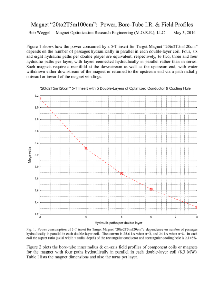
Magnet “20to2T5m100cm”: Power, Bore-Tube I.R. & Field Profiles Bob Weggel Magnet Optimization Research Engineering (M.O.R.E.), LLC May 3, 2014 Figure 1 shows how the power consumed by a 5-T insert for Target Magnet “20to2T5m120cm” depends on the number of passages hydraulically in parallel in each double-layer coil. Four, six and eight hydraulic paths per double player are equivalent, respectively, to two, three and four hydraulic paths per layer, with layers connected hydraulically in parallel rather than in series. Such magnets require a manifold at the downstream as well as the upstream end, with water withdrawn either downstream of the magnet or returned to the upstream end via a path radially outward or inward of the magnet windings. "20to2T5m120cm" 5-T Insert with 5 Double-Layers of Optimized Conductor & Cooling Hole 9.2 9.0 8.8 8.6 Megawatts 8.4 8.2 8.0 7.8 7.6 7.4 7.2 3 4 5 6 7 8 Hydraulic paths per double layer Fig. 1. Power consumption of 5-T insert for Target Magnet “20to2T5m120cm”: dependence on number of passages hydraulically in parallel in each double-layer coil. The current is 25.6 kA when n=3, and 24 kA when n=8. In each coil the aspect ratio (axial width ÷ radial depth) of the rectangular conductor and rectangular cooling hole is 2.1±5%. Figure 2 plots the bore-tube inner radius & on-axis field profiles of component coils or magnets for the magnet with four paths hydraulically in parallel in each double-layer coil (8.3 MW). Table I lists the magnet dimensions and also the turns per layer. Target Magnet "20to2T5m120cm": Bore-Tube Radius and On-Axis Field Profiles 25.0 22.5 On-axis field [T]; Bore-tube I.R. [cm] 20.0 17.5 15.0 SC coil #1 Total field Cu magnet SC magnet Bore tube I.R. 12.5 10.0 7.5 5.0 2.5 0 -200 -100 0 100 200 300 400 500 600 700 800 900 1000 Distance from field maximum [cm] Fig. 2. Target Magnet “20to2T5m120cm”: Bore-tube I.R. & on-axis field profiles of component coils or magnets. Table I: Selected parameters of Target Magnet “20to2T5m120cm” SS shell thickness cm 0.316 0.401 0.419 0.452 0.476 Upstream end cm -80.54 -80.54 -80.54 -80.54 -80.54 -202.0 138.2 457.9 636.4 663.5 724.7 952. 0 Length of solenoid cm 160.6 160.6 160.6 160.6 160.6 340.1 81.37 165.7 21.98 53.30 215.4 15.00 Downstream end cm 80.10 80.10 80.10 80.10 80.10 138.2 219.5 623.6 658.3 716.8 940.1 967.0 Gap between coils cm 0 238.4 12.76 5.14 7.92 11.86 Turns/layer cm 35.74 33.89 31.52 29.99 28.75 Inner radius cm 16.00 21.46 27.17 33.19 39.46 120.0 120.0 120.0 120.0 120.0 120.0 120.0 2.00 2.00 2.00 2.00 2.00 Layers of hollow cond. Radial depth of coil cm 5.143 5.314 5.596 5.819 6.062 79.94 59.32 3.002 5.272 3.762 3.496 15.98 O. R. without SS shell cm 21.14 26.77 32.77 39.01 45.52 199.9 179.3 123.0 125.3 123.8 123.5 136.0 O. R. with SS shell cm 21.46 27.17 33.19 39.46 46.00


