2.2.5.P Fireplace Control Circuit
advertisement

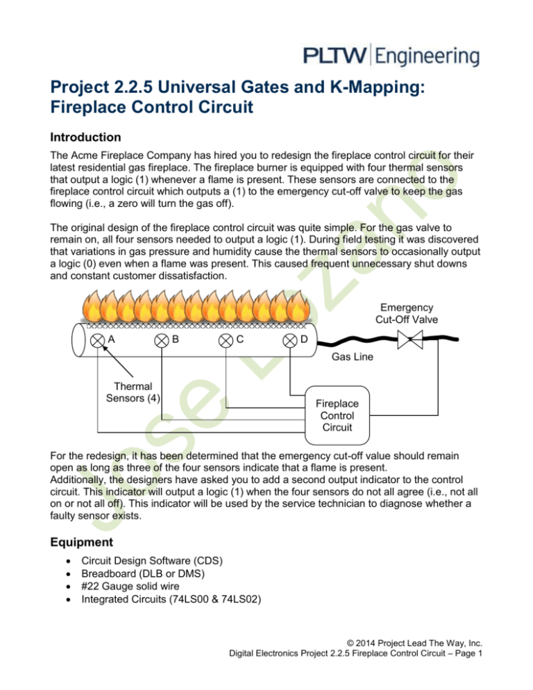
Project 2.2.5 Universal Gates and K-Mapping: Fireplace Control Circuit Introduction The Acme Fireplace Company has hired you to redesign the fireplace control circuit for their latest residential gas fireplace. The fireplace burner is equipped with four thermal sensors that output a logic (1) whenever a flame is present. These sensors are connected to the fireplace control circuit which outputs a (1) to the emergency cut-off valve to keep the gas flowing (i.e., a zero will turn the gas off). The original design of the fireplace control circuit was quite simple. For the gas valve to remain on, all four sensors needed to output a logic (1). During field testing it was discovered that variations in gas pressure and humidity cause the thermal sensors to occasionally output a logic (0) even when a flame was present. This caused frequent unnecessary shut downs and constant customer dissatisfaction. Emergency Cut-Off Valve A B C D Gas Line Thermal Sensors (4) Fireplace Control Circuit For the redesign, it has been determined that the emergency cut-off value should remain open as long as three of the four sensors indicate that a flame is present. Additionally, the designers have asked you to add a second output indicator to the control circuit. This indicator will output a logic (1) when the four sensors do not all agree (i.e., not all on or not all off). This indicator will be used by the service technician to diagnose whether a faulty sensor exists. Equipment Circuit Design Software (CDS) Breadboard (DLB or DMS) #22 Gauge solid wire Integrated Circuits (74LS00 & 74LS02) © 2014 Project Lead The Way, Inc. Digital Electronics Project 2.2.5 Fireplace Control Circuit – Page 1 Procedure Design Design a combinational logic circuit that meets the above detailed design specifications. Additionally: The Karnaugh mapping technique must be used to obtain the simplified logic expression for both outputs. The circuit that controls the emergency cut-off valve must be implemented using only 74LS00 two-input NAND gates. The circuit for the possible faulty sensor indicator must be implemented using only 74LS02 two-input NOR gates. Simulation Using the Circuit Design Software (CDS), enter and test your Fireplace Control Circuit design. Use switches for the inputs A, B, C, and D and a probe or LED circuit for the two outputs. Verify that the circuit is working as designed. If it is not, review your design work and circuit implementation to identify your mistake. Make any necessary corrections and retest. Be sure to document all changes in your engineering notebook/portfolio. Prototyping Using a Digital Logic Board (DLB) or Digital MiniSystem (DMS), build and test your Fireplace Control Circuit design. Verify that the circuit is working as designed. If it is not, YOU SHOULD NOT CHANGE YOUR DESIGN. You know that your design functions because you simulated it. If your circuit isn’t working correctly, you must have built something incorrectly. Review your circuit implementation to identify your mistakes, make the necessary corrections, and retest. Be sure to document all changes in your engineering notebook/portfolio. Conclusion Using your engineering notebook/portfolio as a guide, write a conclusion (minimum 250 words) that describes the process that you used to design, simulate, and build your Fireplace Control Circuit. This conclusion must include all of your design work (i.e., truth table, K-Maps, etc.), preliminary and final schematics, parts list, and a digital photograph of your final circuit. The documentation should be complete enough that a student with a similar knowledge of digital electronics could reproduce your design without any additional assistance. © 2014 Project Lead The Way, Inc. Digital Electronics Project 2.2.5 Fireplace Control Circuit – Page 2 Elaborate Explanation In the “Activity 2.2.5 Fireplace Control Circuit”, I used many different techniques that helped me to reach the final product. Amazingly the design worked and it was true to the truth tables that I made before the design. First to the important things to do is to make a truth table for the Emergency Cutoff valve and the Faulty circuit Indicator. Like these: BC’+A’D+AB’+CD’ ABD+ABC+BCD+ACD Figure. 1 Next using those truth tables create the corresponding Un-simplified logic expressions. Once you have found the Unsimplified expressions, simplify them using the K-mapping technique. This technique can easily simplify expressions without using Boolean algebra or De Morgan’s Theorems. And Now that you have the simplified Expressions (as seen in figure 1) you can go to the Circuit Design Software and prepare the circuit to test out. These are the Circuits that I got from those truth tables and k-maps. Once you have this get your breadboard ready and place your circuit there according to the schematic you made on cds. And the working end result should be: VCC 5V S1 1 U1A Key = S2 Space 3 74LS00N 2 GND U1B 5 74LS00N 7 U1C U2A Key = Space VCC S4 6 U1D 8 74LS00N 74LS00N 4 U2D X1 15 2.5 V U4A 17 74LS00N Key = S3 Space 74LS00N 11 74LS00N U3C U2B U3D 14 12 Key = Space 74LS00N 16 U3A 10 9 74LS00N 74LS00N 74LS00N GND VCC 5V A U5A 18 Key = Space 22 74LS02N B 19 Key = Space C D 24 74LS02N U7B 26 74LS02N 33 U6C 74LS02N 34 25 74LS02N U6D U7C 2.5 V U8B 32 30 74LS02N U5D 74LS02N U7A 29 74LS02N U5C 21 U6B U8A 74LS02N Key = Space Key = Space 28 X2 23 20 U6A 74LS02N U5B GND U3B 74LS00N U2C VCC 13 74LS00N 35 74LS02N U7D 27 31 74LS02N 74LS02N 74LS02N GND © 2014 Project Lead The Way, Inc. Digital Electronics Project 2.2.5 Fireplace Control Circuit – Page 3 © 2014 Project Lead The Way, Inc. Digital Electronics Project 2.2.5 Fireplace Control Circuit – Page 4


