Task 13
advertisement
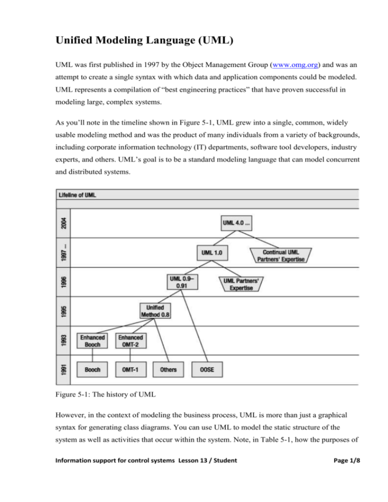
Unified Modeling Language (UML) UML was first published in 1997 by the Object Management Group (www.omg.org) and was an attempt to create a single syntax with which data and application components could be modeled. UML represents a compilation of “best engineering practices” that have proven successful in modeling large, complex systems. As you’ll note in the timeline shown in Figure 5-1, UML grew into a single, common, widely usable modeling method and was the product of many individuals from a variety of backgrounds, including corporate information technology (IT) departments, software tool developers, industry experts, and others. UML’s goal is to be a standard modeling language that can model concurrent and distributed systems. Figure 5-1: The history of UML However, in the context of modeling the business process, UML is more than just a graphical syntax for generating class diagrams. You can use UML to model the static structure of the system as well as activities that occur within the system. Note, in Table 5-1, how the purposes of Information support for control systems Lesson 13 / Student Page 1/8 UML diagrams correspond with the existing Integration DEFinition (IDEF) family of modeling syntaxes. Table 5-1: Comparing UML Diagrams and IDEF Diagrams UML Diagram What It Contains IDEF Model Equivalent Structural Diagrams Class diagram The static objects with their attributes and their relationships to other objects IDEF1: Conceptual Modeling IDEF1X: Logical Modeling IDEF1X97: Logical Modeling with Object Extensions Component diagram Physical software and hardware component dependencies and organization Object diagram Relationships between system objects Deployment diagram Physical system runtime architecture, which can include hardware and software details Behavior Diagrams Activity diagram System activities or business processes and the workflows that connect these processes IDEF0: Activity Modeling Use case diagram Business processes that will be implemented and the people who will interact with them IDEF3: Process Modeling State chart diagram The details surrounding the transition of objects from one business state to another IDEF3: Process Modeling Collaboration diagram The details of how individual objects collaborate and interact Sequence diagram The details of the specific sequencing of messages sent between objects in the system IDEF3: Process Modeling Notice that the IDEF notations can’t capture the same richness of information about the physical software implementation as UML. Also, the shortcoming of the IDEF suite of models is that the information gathered about a process can’t be easily shared with other processes. The IDEF models were designed to be used independently from each other, but UML tries by design to keep the information together and integrated. This allows for multiple different views or perspectives of the same base system information. UML Syntax Information support for control systems Lesson 13 / Student Page 2/8 When comparing UML class diagrams to relational data models, it’s important to understand what’s common to the two styles of modeling and what isn’t. Because of the nature of OOD, some of the concepts you’re able to model in class diagrams, such as class behaviors or complex object data types, aren’t easily represented in a Logical data model. But although the notations aren’t 100 percent compatible, a significant degree of overlap exists in the fundamental areas. Later in this chapter, in the “Example UML Transformation” section, we’ll show how to convert a Logical data model into a UML diagram, but before we do that, we’ll discuss some of the conceptual similarities between object models and relational models. Classes vs. Entities Classes are roughly equivalent to Logical modeling entities, as shown in Figure 5-2. When looking at a business-oriented model, they’re the items that are important to the business. Figure 5-2: How classes and entities are similar Class is a named rectangle with compartments for attributes, operations, and other characteristics, as shown in Figure 5-3. Figure 5-3: Classes and entities with attributes For object classes, you’ll see three distinct areas for each class in the diagram. The top section names the class, the middle section shows the attributes that are part of the class, and the bottom section shows the behaviors or operations that can be performed on that class. Note that no key determination appears on a class, just as no operations appear as part of an entity’s definition. Generalizations vs. Categories Information support for control systems Lesson 13 / Student Page 3/8 In previous lessons you saw how slightly different entities with common attributes can be represented by a category structure, where each subtype is related to its supertype by an “is a” phrase. In UML, categories are represented by generalizations. In both relational and object models, these constructs denote a categorization mechanism representing a hierarchy of supertypes and subtypes (see Figure 5-4). Figure 5-4: UML generalization notation See Figure 5-5 for an example of how this type of relationship is represented in both object and relational models. These hierarchies are always read with an “is a” phrase between the subordinate and generalized Class. For example, Motorcycle “is a” Powered Vehicle. Truck “is a” Powered Vehicle. Cookie “is a” Dessert. Ice Cream “is a” Dessert. Figure 5-5: Inclusive hierarchies in UML and IDEF1X Generalizations denote the distinctness of recognizably different members within a larger, more generic grouping by using an arrow to point to the higher, more encompassing class. An object that’s a single instance of the class in Figure 5-5 may actually be both of the subtypes simultaneously. In relational modeling this is equivalent to an inclusive category. For instance, a Ford Ranchero may belong to both Truck and Automobile depending on the definition of each. To show that an instance of a class may be one and only one of the listed subtypes, use the OR notation, as shown in Figure 5-6. Information support for control systems Lesson 13 / Student Page 4/8 Figure 5-6: UML exclusive generalization notation This notation is equivalent to the IDEF1X double-line category symbol, as shown in Figure 5-7. Figure 5-7: Exclusive generalization in UML and IDEF1X A generalization notation with the dotted line and OR statement notes that a member of the generalized class may belong to only one or the other of the subordinates. This is referred to as an exclusive hierarchy in both UML and IDEF1X. You’d use this notation to show that a Dachshund, for example, can only ever be classified as Dog in the category of Pet. Relationships vs. Associations Similarly to relational models, UML models allow objects to be related, and UML has notation that allows a slightly richer set of relationships to be documented in a UML class diagram. UML has three types of relationships. Associations connect objects that are related but where no dependency exists between the classes taking part in the relationship. For example, an employee is related to an employer, but no existence dependency exists between them. Compositions show that a parent-child relationship exists and that the child entities depend on the parent for their existence. For example, a building contains a series of rooms. If the building is demolished, the rooms that were part of the building also cease to exist. Aggregations show that a group-member relationship exists and that the group entities depend on their members for their existence. For example, the chess club is an aggregation of students, but if the chess club ceased to exist, the students would still exist. If the students ceased to exist, the club also would cease to exist. Information support for control systems Lesson 13 / Student Page 5/8 Relational graphic notations, such as IDEF1X or IE, don’t have a method for noting aggregations. Other than in text blocks or diagram notes, IDEF1X lacks the ability to show that some relationships are built because of a “binding” of the elements for the purpose of creating a grouping entity. Relational modeling techniques recognize only entities connected in some kind of a parent-child relationship or a supertype-subtype hierarchy. These techniques make assumptions regarding the dependence of the child on the parent or regarding the subtype on the supertype. They’re missing the notion of a high-level group that depends on its members for existence. Associations As mentioned, associations show that two objects are connected in some way. An association is equivalent to a relationship line between entities on a relational data model. A solid line shows an association relationship between two objects (see Figure 5-8). Figure 5-8: UML association notation The lack of specific diagram notation at either end of the relationship indicates no dependence between these entities (see Figure 5-9). Figure 5-9: Ordinary association in UML and IDEF1X In a class diagram, the cardinality of the relationship is shown through the use of the numbers at either end of the association line. In Figure 5-9, ClassA is related to ClassB in a one-to-many relationship. Exactly one ClassA object must exist for every ClassB object, and zero or more ClassB objects may exist for every ClassA object. Compositions Information support for control systems Lesson 13 / Student Page 6/8 Composition relationships, also known as strong associations, are the type of relationship that’s most easily translated between UML and relational models. Composition relationships establish a parent-child relationship, where the child depends on the parent for its existence. The dependence is strong enough that it implies that by deleting the parent instance, any child instances will be deleted as well (see Figure 5-10). Figure 5-10: UML composition notation A composition relationship uses a solid diamond notation to identify the owning, parent class. Cardinality symbols as used in association relationships are also used in this example to show the cardinality of the relationship, although the use of a composition requires that the parent entity be marked with a one (see Figure 5-11 and Figure 5-12). Figure 5-11: Recursive composition in UML and IDEF1X Figure 5-12: Nonrecursive composition in UML and IDEF1X The examples in Figures 5-11 and 5-12 show both a recursive composition relationship and a regular nonrecursive composition relationship. In the model, the solid diamond indicates that a Room is dependent on its associated Building for the Room’s existence. If the building were to cease to exist, any Room objects related to it through this composition would also cease to exist. Information support for control systems Lesson 13 / Student Page 7/8 Aggregations Aggregation relationships, also known as weak associations, establish a group-member relationship between objects, where the parent entity depends on the children for its existence. This type of aggregation is noted with a hollow diamond (see Figure 5-13). Figure 5-13: UML shared aggregation notation An aggregation relationship uses a hollow diamond notation to identify the parent class. Cardinality symbols, as used in association relationships, are also used to show the cardinality of the relationship (see Figure 5-14). Figure 5-14: Shared aggregation in UML and IDEF1X A member of an aggregation may be included in several aggregates simultaneously. This “weakened” relationship allows the child members to survive a deletion of its aggregate. This concept isn’t completely compatible with IDEF1X notation, but Figure 5-14 shows as close an equivalent as you can get. Information support for control systems Lesson 13 / Student Page 8/8

