EELE 262 – Logic Circuits Lab
advertisement
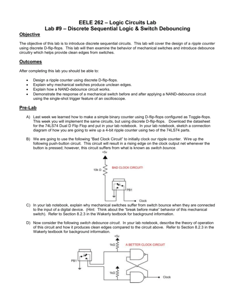
EELE 262 – Logic Circuits Lab Lab #9 – Discrete Sequential Logic & Switch Debouncing Objective The objective of this lab is to introduce discrete sequential circuits. This lab will cover the design of a ripple counter using discrete D-flip-flops. This lab will then examine the behavior of mechanical switches and introduce debounce circuitry which helps provide clean edges from switches. Outcomes After completing this lab you should be able to: Design a ripple counter using discrete D-flip-flops. Explain why mechanical switches produce unclean edges. Explain how a NAND-debounce circuit works. Demonstrate the response of a mechanical switch before and after applying a NAND-debounce circuit using the single-shot trigger feature of an oscilloscope. Pre-Lab A) Last week we learned how to make a simple binary counter using D-flip-flops configured as Toggle-flops. This week you will implement the same circuits, but using discrete D-flip-flops. Download the datasheet for the 74LS74 Dual D Flip Flop and put in your lab notebook. In your lab notebook, sketch a connection diagram of how you are going to wire up a 4-bit ripple counter using two of the 74LS74 parts. B) We are going to use the following “Bad Clock Circuit” to initially clock our ripple counter. Wire up the following push-button circuit. This circuit will result in a rising edge on the clock output net whenever the button is pressed; however, this circuit suffers from what is known as switch bounce. C) In your lab notebook, explain why mechanical switches suffer from switch bounce when they are connected to the input of a digital device. (Hint: Think about the “break before make” behavior of this mechanical switch). Refer to Section 8.2.3 in the Wakerly textbook for background information. D) Now consider the following switch debounce circuit. In your lab notebook, describe the theory of operation of this circuit and how it produces clean edges compared to the circuit above. Refer to Section 8.2.3 in the Wakerly textbook for background information. EELE 262 – Logic Circuits Lab Lab #9 – Discrete Sequential Logic & Switch Debouncing ______________________________________________________________________________________________________ Lab Work & Demonstration 1) Breadboard your 4-bit ripple counter and use the push button circuit from part B to provide the clock. You should display the 4-bit output of your counter on the LEDs of your breadboard. You will see a sporadic count due to the unclean edges coming from the bouncy button. Use the oscilloscope to show the unclean clock edges going into your ripple counter. You will need to setup the oscilloscope to perform a single trigger when it sees a rising edge. Show the lab instructor the output of the push button on the oscilloscope and describe why you are observing some of the voltage levels you are seeing (e.g., why isn’t it simply GND or +5v?) TA will check off 2) Now breadboard the switch debounce circuit from part D and use it to clock your ripple counter. You should see the counter increment by 1 each time you press the button. Use the oscilloscope to show the clean edges going into your ripple counter. Show the lab instructor the output of the push button on the oscilloscope and describe why you are observing the signal you are seeing (e.g., a clean edge and properly operating ripple counter). TA will check off 3) Now use the AWG to drive the clock to your ripple counter at a frequency of 2Hz. Remember to setup the AWG correctly so you don’t overdrive your D-flip-flops! TA will check off Lab Grading Pre-Lab ___________ / 10 Lab Demo (step 1) Lab Demo (step 2) Lab Demo (step 3) ___________ / 40 ___________ / 40 ___________ / 10 Total ___________ / 100 2


