University of Leicester PLUMERef: PLM-PSU_EIecInter-317
advertisement
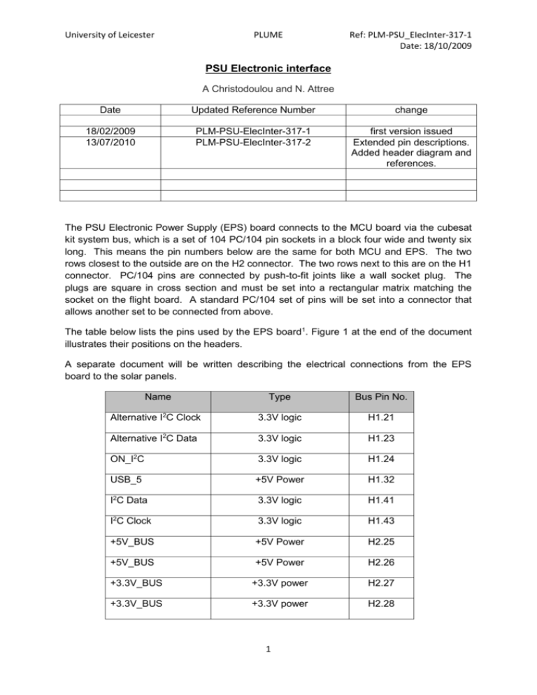
University of Leicester PLUME Ref: PLM-PSU_EIecInter-317-1 Date: 18/10/2009 PSU Electronic interface A Christodoulou and N. Attree Date Updated Reference Number change 18/02/2009 13/07/2010 PLM-PSU-ElecInter-317-1 PLM-PSU-ElecInter-317-2 first version issued Extended pin descriptions. Added header diagram and references. The PSU Electronic Power Supply (EPS) board connects to the MCU board via the cubesat kit system bus, which is a set of 104 PC/104 pin sockets in a block four wide and twenty six long. This means the pin numbers below are the same for both MCU and EPS. The two rows closest to the outside are on the H2 connector. The two rows next to this are on the H1 connector. PC/104 pins are connected by push-to-fit joints like a wall socket plug. The plugs are square in cross section and must be set into a rectangular matrix matching the socket on the flight board. A standard PC/104 set of pins will be set into a connector that allows another set to be connected from above. The table below lists the pins used by the EPS board1. Figure 1 at the end of the document illustrates their positions on the headers. A separate document will be written describing the electrical connections from the EPS board to the solar panels. Name Type Bus Pin No. Alternative I2C Clock 3.3V logic H1.21 Alternative I2C Data 3.3V logic H1.23 ON_I2C 3.3V logic H1.24 USB_5 +5V Power H1.32 I2C Data 3.3V logic H1.41 I2C Clock 3.3V logic H1.43 +5V_BUS +5V Power H2.25 +5V_BUS +5V Power H2.26 +3.3V_BUS +3.3V power H2.27 +3.3V_BUS +3.3V power H2.28 1 University of Leicester PLUME Ref: PLM-PSU_EIecInter-317-1 Date: 18/10/2009 GND Digital Ground H2.29 GND Digital Ground H2.30 Analogue Ground H2.31 Digital Ground H2.32 VBAT(PP_NC) Launch switch connections H2.33 VBAT(PP_NC) Launch switch connections H2.34 VBAT(SS_NC) Launch switch connections H2.35 VBAT(SS_NC) Launch switch connections H2.36 VBAT(PP_SS_C) Launch switch connections H2.41 VBAT(PP_SS_C) Launch switch connections H2.42 VBAT(PP_SS_C) Launch switch connections H2.43 VBAT(PP_SS_C) Launch switch connections H2.44 BAT_BUS Battery Voltage Unregulated H2.45 BAT_BUS Battery Voltage Unregulated H2.46 AGND GND The maximum rating of the PC/104 system bus is no more than 3A, and between -0.3 to 3.6V, except on the 5V logic pins. The operating temperature of the MCU is between -40 and +850C. PC/104 buses are stackable in that several can be fitted one on top of another. Pin Descriptions Pins H1.1-20, 22, 25-31, 33-40, 42 and 44-46 as well as H2.1-24, 31, 37-40 and 49-52 are not used by the PSU and are therefore not connected to anything on the EPS board. Pins H1.47-52 and H2.47-48 are not used as they synchronise stacked power boards when multiple EPS boards are used. H1.41 and H1.43 or H1.21 and H1.23 may be used for I2C communications with the TTC node but if the alternative pins are used they must be connected to 41 and 43 by 0 ohm resistors (wire). H1.24 (ON_I2C) can be used to manually turn the TTC node on and off but is not normally needed as the node should activate itself2. H1.32 can be used to power the board and charge the battery via USB whilst testing. H2.25, H2.26, H2.27 and H2.28 are all connected to the power buses (5V for the first two and 3.3V for the second pair). Pins H2.33 to H2.44 are connected to the remove before flight and launch switches, and may be able to directly send a command signal to hardware 2 University of Leicester PLUME Ref: PLM-PSU_EIecInter-317-1 Date: 18/10/2009 without the MCU being active, though this is uncertain at the time of documentation. For the board to fully function during testig H2.41-44 (battery common) must be shorted to pins H2.33-36 (separation switch and pull pin connections). H2.45 and H2.46 connect to the unregulated output bus of the batteries. Figure 1. Diagram of pins used on EPS board from Clyde Space documentation. Colour coded by Green: ground, Light Blue: I2C pins, Red: USB, Purple: power pins, Other: launch switch connections. Testing During testing push-connect headers with soldered wire connections are used to simulate closing the separation switch and activating the pull pin as described above. Other connections are also made from these headers to other equipment as needed as described in the PSU test plan. References 1. Clyde Space Manual, Issue K. Contact Nick Attree to obtain a copy. 2. From personal correspondence with Kevin Worrall at Clyde Space. 3


