Creating a New Well Section Window
advertisement

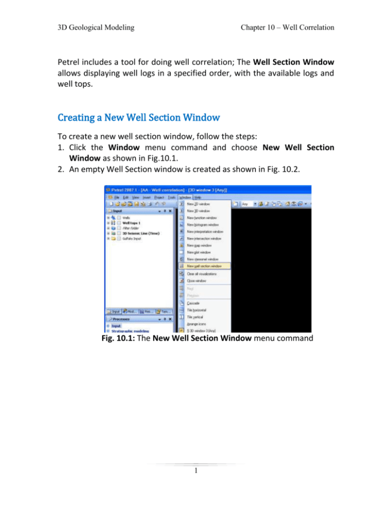
Chapter 10 – Well Correlation 3D Geological Modeling Petrel includes a tool for doing well correlation; The Well Section Window allows displaying well logs in a specified order, with the available logs and well tops. Creating a New Well Section Window To create a new well section window, follow the steps: 1. Click the Window menu command and choose New Well Section Window as shown in Fig.10.1. 2. An empty Well Section window is created as shown in Fig. 10.2. Fig. 10.1: The New Well Section Window menu command 1 Chapter 10 – Well Correlation 3D Geological Modeling Fig. 10.2: An empty Well Section window 2 Chapter 10 – Well Correlation 3D Geological Modeling Displaying Logs and Tops There are two ways to display Logs: a. To populate the window with well logs, 1. Expand the Wells folder in the Input Pane. 2. Choose the wells to be added to the section. For example, select the wells B9, C4, C2, A10 and C5. Notice: that whenever a well is clicked, it is directly sorted under the Well Section folder in the Windows Pane as shown in Fig. 10.3. Fig.10.3: Some wells displayed in the Well Section window 3 Chapter 10 – Well Correlation 3D Geological Modeling 3. Now select the logs to be displayed for all wells from the Global Well logs folder under the Wells folder as show in Fig. 10.4. Fig.10.4: Well logs of well C2 displayed in the Well Section window 4 Chapter 10 – Well Correlation 3D Geological Modeling b. Alternatively, well sections are created interactively by clicking them on a 3D window: 1. Create a New Well Section Window. 2. Display all wells in a 3D window. 3. Activate the Well Correlation process under the Stratigraphic Modeling in the Processes Pane. 4. Click Add well to well section icon on the Well correlation 3D tools toolbar. And now select the wells to be added to the well section. In this case, click the wells C5, A10, B9, C4 and C2. Fig.10.5: The Wells Displayed in the 3D Window with the Tool bar 5 Chapter 10 – Well Correlation 3D Geological Modeling Display the Well Tops by toggling on the checkbox in front of the Well Tops folder as shown by Fig. 10.6. Fig. 10.6: Well Tops displayed in the Well Section window 6 Chapter 10 – Well Correlation 3D Geological Modeling Scrolling and Zooming The well log display can be scrolled or zoomed. Scrolling and/or zooming may be done for each log individually or synchronized for all logs. When scrolling and zooming, you will use the gray and white scroll bar on the left side of each well panel. The larger the white area as compared to the gray area, the larger is the displayed proportion of the well. When the entire bar is white, then the entire well is being displayed. To scroll one single well: position the cursor over the white area in the scroll bar. A hand will appear. Press the left mouse button to scroll up and down as shown in Fig. 10.7. To zoom one single well: Position the cursor over the border between the white and gray area in the scroll bar. A double arrow will appear. Press the left mouse button over the white/gray border to zoom in/out as shown in Fig. 10.7. Fig. 10.7: Scrolling the well up and down 7 Chapter 10 – Well Correlation 3D Geological Modeling Fig. 10.8: Zooming in and out 8 Chapter 10 – Well Correlation 3D Geological Modeling Grouping of Logs Several logs can be grouped into a single panel; e.g. Neutron and Density logs may be grouped to distinguish between shale and non-shale intervals. To create a group panel, follow the steps: 1. Make the Well Section active. 2. Right click on the well name; e.g. well C2 under the well section. 3. Choose Insert track panel. Fig.10.9: Insert Track Panel for well C2 9 Chapter 10 – Well Correlation 3D Geological Modeling 4. A track1 panel is created. 5. Drag and drop the required logs into the Track icon; e.g. Porosity and Gamma logs. 5 2 4 Fig.10.10: Track 1 is created 6. Change the track name from Info tab to Gamma & Porosity by double clicking on the Track 1 and expand it to see the inserted log curves icons. Fig.10.11: Gamma & Porosity after group it in one Track Panel 10 Chapter 10 – Well Correlation 3D Geological Modeling 7. The track panel and the selected log curves will now be visible in the Well Section window as shown in Fig. 10.12. Fig.10.12: Gamma & Porosity log curves displayed in a Well Section window 11 Chapter 10 – Well Correlation 3D Geological Modeling Flatten on a Horizon To scroll all logs simultaneously, you need to flatten the logs to a horizon. To do this, follow the steps: 1. Display the Well Section window. 2. Display well tops in the well section window. 3. Right click on the Well Section in the Process Pane and select Settings from the drop down menu. Fig.10.13: Settings for well Section 1 12 Chapter 10 – Well Correlation 3D Geological Modeling 4. When the Settings dialog box appears, select the Settings tab. 5. Click Flatten on well top radio button, see Fig. 10.14. 6. Go to the Input Pane and select the well top to flatten all well logs to for example select Base Cretaceous. Fig. 10.14: Settings for the Well Section window 13 Chapter 10 – Well Correlation 3D Geological Modeling 7. Click the Apply button; note that all logs will be flattened to the Base Cretaceous horizon, as shown in Fig. 10.15. Fig. 10.15: All logs flattened to the Base Cretaceous horizon 14 Chapter 10 – Well Correlation 3D Geological Modeling Coloring of Logs Color fill can be applied to areas between the panel edge and the log and/or between logs. For example, to fill color in the interval between two curves, follow the steps: 1. Open the Settings of one of the in the track panel (Gamma & Porosity). 2. Go to the "Curve filling" tab. 3. Enter a new interval and specify the interval to be filled as shown in Fig. 10.16. 4. From Fill edge choose Curve option. 5. Go to Fill style option and choose Fill pattern color and the Fill color that is desirable, and click the Apply button. 3 4 5 Fig.10.16: Settings for Gamma & Porosity 15 Chapter 10 – Well Correlation 3D Geological Modeling 6. Repeat the same processes that you did before but you have to change from Gamma - Porosity to Porosity -Gamma as shown in Fig. 10.17. Then press OK. Fig.10.17: Settings for Gamma & Porosity 16 Chapter 10 – Well Correlation 3D Geological Modeling 7. The color and pattern change accordingly as shown in Fig. 10.18. Fig. 10.18: Gamma & Porosity log curves is filled with the specified color & pattern 17 Chapter 10 – Well Correlation 3D Geological Modeling Similarly, for panels containing one well log only, to color in the interval between the log and the left panel edge, follow the steps: 1. Select the Create/edit curve fill icon. 2. Click in the area between the left edge and the Perm log to fill color in that interval as shown in Fig. 10.19. Fig. 10.19: The area between log curves is filled with the specified color & pattern 18 Chapter 10 – Well Correlation 3D Geological Modeling Edit/Add Well Tops in Well Section Windows Well Tops can be edited by positioning the cursor on one of the well tops. An arrow will appear ( ). When the arrow is showing, move the well top to the required position. Edit Well Tops To edit well tops in the well section window, follow the steps: 1. Display the well whose well top is to be edited; in this case display C5, A10, B9, C4 and C2Display Well Tops under Well Tops folder. 2. Activate the Create/edit well tops [T] icon as shown in Well corr.2D tools toolbar below. When the mouse Hoovers on the well top, the double arrow ( ) appears, 3. Click on Create/edit well tops [T] icon to move the well tops as shown in Fig. 10.20. 19 Chapter 10 – Well Correlation 3D Geological Modeling Fig. 10.21: Displaying existing Well Tops in a Well Section window 20 Chapter 10 – Well Correlation 3D Geological Modeling Fig.10.22: Displaying existing Well Tops (flattened together) in a Well Section window 21 Chapter 10 – Well Correlation 3D Geological Modeling Add Well Tops To add a new well top, follow the steps: 1. Click on the Add new well tops surface [S] icon as shown in Fig. 10.20. Note that the Create/Edit well tops icon must be active in order to get access to the Add new well tops icon. 2. Insert a new well top by clicking on the position where it should be inserted. Note that if one of your well tops in the Well Tops folder is active, the new well top will create as the same name as shown in Fig. 10.21. 3. To insert new well tops with a new name, make sure to de-activate the existing well tops as shown in Fig. 10.23. Fig. 10.23: Inserting new Well Tops in a Well Section window 22 Chapter 10 – Well Correlation 3D Geological Modeling Fig. 10.24: Displaying the new Well Tops, for Top Ness in a Well Section window 23 Chapter 10 – Well Correlation 3D Geological Modeling Fig. 10.25: Displaying the new Well Tops in a Well Section window 24 Chapter 10 – Well Correlation 3D Geological Modeling The settings of Well Correlation may be changed by: 1. Right click on the one of the wells for example C5 on the windows pane. 2. Choose Insert Rose diagram. Fig.10.26: Insert Rose diagram panel for well C5 25 Chapter 10 – Well Correlation 3D Geological Modeling 3. You can display the Rose diagram by two ways: Logs or Well tops. For example we will displayed by logs option for Gamma Fig.10.27: Settings for “Rose diagram panel”. 26 Chapter 10 – Well Correlation 3D Geological Modeling Fig.10.28: Displaying Rose diagram in well section for well C5 27 Chapter 10 – Well Correlation 3D Geological Modeling Interactive Facies Interpretation To edit an exiting facies log: Activate the Paint, Flood or Pick discrete log class icon. Select facies by right clicking the mouse. Start edit on the log. 1. 2. 3. 4. To create a new discrete log: Click on the Paint discrete log, Pick up discrete log class, or Flood fill discrete log icon as shown in the Well corr. 2D tools toolbar below, The Create new discrete log icons will activate. Press on the Create new discrete log icon. A window will pop up in which you should specify the type of log to be created. In this case, choose fluvial facies as shown in Fig. 10.24. Press OK. The new log will be placed under the Global Well Logs folder. See Fig. 10.26. 28 Chapter 10 – Well Correlation 3D Geological Modeling Fig. 10.29: Creating a new discrete log 29 Chapter 10 – Well Correlation 3D Geological Modeling Fig. 10.30: Fluvial facies log is empty and placed under the Global Well Logs folder Now spend sometime to display the logs that give information about the facies. Draw the different facies in the correct positions. See Fig. 10.29. 30 Chapter 10 – Well Correlation 3D Geological Modeling .Fig. 10.31: Settings for "Fluvial facies" dialog box is displayed Fig. 10.32:The Fluvial facies log drawing process while the Settings for "Fluvial facies"dialog box is displaye 31


