Types of optical fibers - Book Spar | Website for students | VTU notes
advertisement
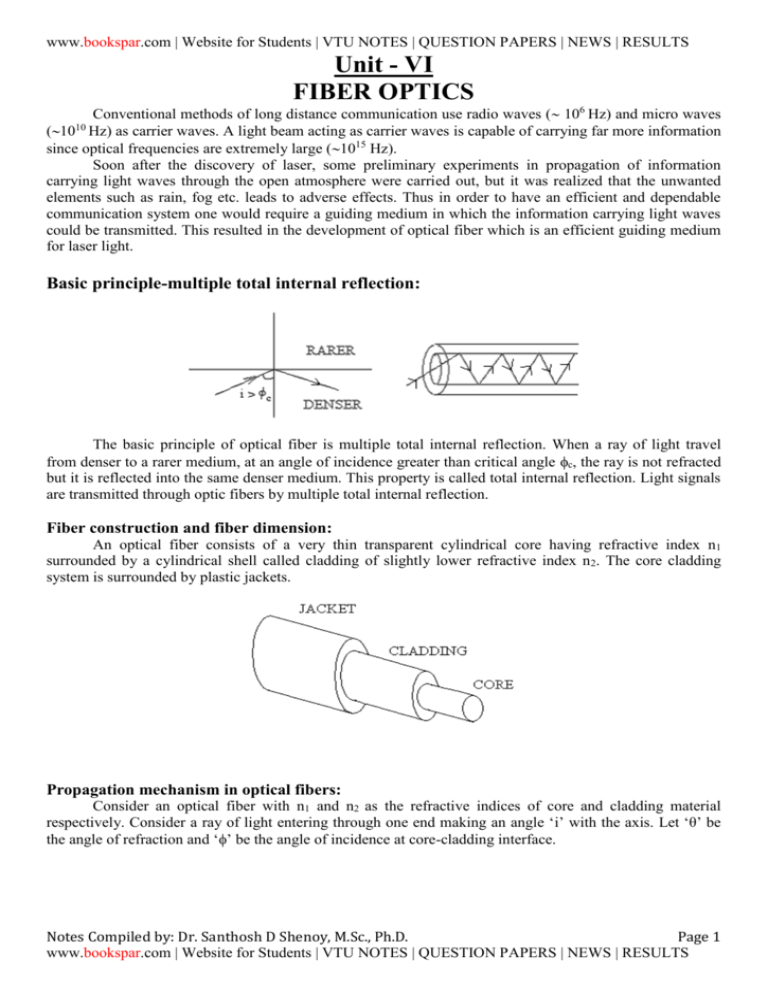
www.bookspar.com | Website for Students | VTU NOTES | QUESTION PAPERS | NEWS | RESULTS
Unit - VI
FIBER OPTICS
Conventional methods of long distance communication use radio waves ( 106 Hz) and micro waves
(1010 Hz) as carrier waves. A light beam acting as carrier waves is capable of carrying far more information
since optical frequencies are extremely large (1015 Hz).
Soon after the discovery of laser, some preliminary experiments in propagation of information
carrying light waves through the open atmosphere were carried out, but it was realized that the unwanted
elements such as rain, fog etc. leads to adverse effects. Thus in order to have an efficient and dependable
communication system one would require a guiding medium in which the information carrying light waves
could be transmitted. This resulted in the development of optical fiber which is an efficient guiding medium
for laser light.
Basic principle-multiple total internal reflection:
The basic principle of optical fiber is multiple total internal reflection. When a ray of light travel
from denser to a rarer medium, at an angle of incidence greater than critical angle c, the ray is not refracted
but it is reflected into the same denser medium. This property is called total internal reflection. Light signals
are transmitted through optic fibers by multiple total internal reflection.
Fiber construction and fiber dimension:
An optical fiber consists of a very thin transparent cylindrical core having refractive index n1
surrounded by a cylindrical shell called cladding of slightly lower refractive index n 2. The core cladding
system is surrounded by plastic jackets.
Propagation mechanism in optical fibers:
Consider an optical fiber with n1 and n2 as the refractive indices of core and cladding material
respectively. Consider a ray of light entering through one end making an angle ‘i’ with the axis. Let ‘θ’ be
the angle of refraction and ‘’ be the angle of incidence at core-cladding interface.
Notes Compiled by: Dr. Santhosh D Shenoy, M.Sc., Ph.D.
Page 1
www.bookspar.com | Website for Students | VTU NOTES | QUESTION PAPERS | NEWS | RESULTS
www.bookspar.com | Website for Students | VTU NOTES | QUESTION PAPERS | NEWS | RESULTS
sin i
By Snell’s law, n1 = sinθ
Or sinθ =
sin i
n1
---------------(1)
n
At core-cladding interface, refractive index µ = n1
2
Total internal reflection takes place at core-cladding interface if the angle of incidence at core-cladding
interface is equal to or greater than critical angle c.
n
1
We have µ = n1 = sin Φ
2
𝑐
n2
sinΦc = n -------------------(2)
1
For total internal reflection to take place,
≥ c
or, sin ≥ sinc
n
i.e., sin Φ ≥ n2
[ from eq(2)]
1
But from the ABC, sin = cos
n
cosθ ≥ 2
i.e., (1-sin )
2
1/2
i.e., (1-sin2)
i.e., sin2
≥
n1
n2
sin2 ≤
n21
2 2
(n1 -n2 ) 1/2
n21
1
(n21 -n22 )2
i.e., sin ≤ (
i.e., sin ≤
)
n1
But from equation (1), sinθ =
sin i
n ≤
1
[since sin2 + cos2 = 1]
n1
n
≥ ( n2 )2
1
n
≤ 1- ( n2 )2
1
(n21 -n22 )
1
(n21 -n22 )2
sin i
n1
n1
sini ≤ (n12-n22)1/2
Or i ≤ sin-1(n12-n22)1/2
Thus if the angle of incidence is greater than sin-1(n12-n22)1/2, total internal reflection and transmission of
light will not take place.
Acceptance angle:
The maximum angle of incidence at which light may enter the fiber in order to be propagated is,
im= sin-1(n12-n22)1/2 and this angle is called acceptance angle for the fiber.
Notes Compiled by: Dr. Santhosh D Shenoy, M.Sc., Ph.D.
Page 2
www.bookspar.com | Website for Students | VTU NOTES | QUESTION PAPERS | NEWS | RESULTS
www.bookspar.com | Website for Students | VTU NOTES | QUESTION PAPERS | NEWS | RESULTS
Numerical aperture:
Numerical aperture of an optical fiber is a measure of its light gathering capacity and it is denoted as
the sine of acceptance angle.
i.e., NA = sin im = (n12-n22)1/2 where n1 is the refractive index of core and
n2 is the refractive index of cladding.
Fractional index change ():
Fractional index change () is the ratio of the refractive index difference between the core and
cladding to the refractive index of the core of an optical fiber.
(𝐧 −𝐧 )
= 𝟏𝐧 𝟐 where n1 is the refractive index of core and
𝟏
n2 is the refractive index of cladding.
Relation between Numerical aperture (NA) and Fractional index change ():
(n −n )
We have Fractional index change, = 1n 2 where n1 is the refractive index of core and
1
n2 is the refractive index of cladding
i.e., (n1– n2) = n1 -------------------- (1)
But Numerical aperture, NA = (n12-n22)1/2
= [(n1+ n2) (n1-n2)] ½
= [(n1+ n2) n1] ½ {Applying equation (1)}
Since, n1 n2, n1+ n2 = 2n1
NA = [2 n12]1/2
NA = n1√𝟐∆
Thus from the above equation it can be observed that increasing the value of ‘∆’, one can increase
the light gathering capacity of an optical fiber. But a large value of ‘∆’ leads to intermodal dispersion, which
causes signal distortion.
Types of optical fibers:
i ) On the basis of materials:
On the basis of materials used for core and cladding, optical fibers are classified into three categories:
1. Glass fibers (glass core with glass cladding)
2. Plastic fibers (plastic core with plastic cladding)
3. PCS fibers (polymer cladding with silica core)
Plastic fibers have the advantage of more flexibility than glass fibers but attenuation is greater in
plastic fibers, comparing with glass fibers.
ii) On the basis of refractive index profile- Step index and graded index fiber
If the optical fiber has a core of uniform constant refractive index n1 and a cladding of slightly lower
refractive index n2, it is called a step index fiber. The cross sectional refractive index profile is as shown:
Notes Compiled by: Dr. Santhosh D Shenoy, M.Sc., Ph.D.
Page 3
www.bookspar.com | Website for Students | VTU NOTES | QUESTION PAPERS | NEWS | RESULTS
www.bookspar.com | Website for Students | VTU NOTES | QUESTION PAPERS | NEWS | RESULTS
If the core of optic fiber has a non-uniform refractive index that decreases gradually from the centre
towards the core-cladding boundary, it is called a graded index (GRIN) fiber. The cladding surrounding the
core has a uniform refractive index, slightly lower than the refractive index of the core. The cross sectional
refractive index profile is as shown:
Modes of propagation:
When the light rays are guided through the fibers, it propagates in different modes. Modes can be
visualized as the possible number of allowed paths of light in an optical fiber. On the basis of the modes of
propagation, optical fibers are classified into two:
1. Single mode fiber that supports only one mode of propagation. For this a step index fiber with small core
diameter (around 10m) is used.
2. Multimode fiber that support a number of modes. For this, a step index fiber with large core diameter
(around 50m) or a graded index (GRIN) fiber is used.
V-number of a multimode fiber:
The number of modes supported for propagation by a multimode fiber is determined by a parameter
called V-number (denoted as V). If the surrounding medium is air, then the V-number is given by,
πd
V= √(n21 -n22 )
λ
where‘d’ is the core diameter, ‘’ is the wavelength of light propagating in the fiber.
The number of modes supported by the fiber is given by,
Number of modes =
V2
2
Attenuation:
Attenuation is the loss of power suffered by the optical signal as it propagates through the fiber. It is
also referred as fiber loss.
10
P
Attenuation co-efficient or attenuation i.e., ∝ = L log P i db/km
0
where Pi is the optical power launched at the input and Po the output power after traveling a distance L km.
Different mechanisms of attenuation:
Notes Compiled by: Dr. Santhosh D Shenoy, M.Sc., Ph.D.
Page 4
www.bookspar.com | Website for Students | VTU NOTES | QUESTION PAPERS | NEWS | RESULTS
www.bookspar.com | Website for Students | VTU NOTES | QUESTION PAPERS | NEWS | RESULTS
1. Absorption: The optical fiber material and the impurities present in the material absorb light leading to
fiber loss.
2. Rayleigh scattering: This occurs due to the local variations in refractive index. The Rayleigh scattering
loss depends on the wavelength. It varies as 1/4 and becomes significant at lower wavelengths. Below
0.8m, the scattering loss is very high.
3. Radiation losses: This occurs due to the bending of the fiber. There are two types of bendsa) Macroscopic and b) Microscopic.
The bends having radii greater compared to the fibre diameter are called macroscopic bends. In such
curved fibers the incident angle falls below the critical angle and no total internal reflections takes place.
Microscopic bending occurs due to non-uniformities in the manufacturing of the fibre where of the
light rays may leak through the fibre. Microscopic bending losses could be minimized by extruding a
compressible jacket over the fibre that will keep the fibre relatively straight.
Dispersion losses due to various modes of propagation:
1) Waveguide dispersion:
In single mode fibers, part of the light ray will be refracted into the cladding. The loss due to this is
referred as waveguide dispersion. Waveguide dispersion is negligible in multimode fibers.
2) Intermodal dispersion:
The intermodal dispersion occurs in multimode fibers where rays associated with various modes
travel different distances through the fiber. As a result, the signal broadens and the output signal is no longer
identical with the input signal. Signal broadening is less in graded index and step index single mode fibers.
3) Material dispersion or chromatic dispersion:
If we use white light, all the colours of the input radiation are not reaching the other end at the same
time since they travel with different velocities. Signal distortion of this kind is called material dispersion or
chromatic dispersion.
Applications of optical fibers:
1. In fiber optic communication
2. In fiber optic sensors
3. For industrial automation
4. In security alarm systems
5. In local area network (LAN) of computers
6. For high speed data transmission in computers
7. Medical applications- for diagnosis and surgical applications (endoscopy)
8. Military applications (fiber guided missiles)
Point to point light wave communication using optic fiber:
A simple block diagram of fiber optic communication system is shown below:
Notes Compiled by: Dr. Santhosh D Shenoy, M.Sc., Ph.D.
Page 5
www.bookspar.com | Website for Students | VTU NOTES | QUESTION PAPERS | NEWS | RESULTS
www.bookspar.com | Website for Students | VTU NOTES | QUESTION PAPERS | NEWS | RESULTS
Optical transmitter:
A light emitting diode (LED) or a semiconductor laser can be used as optical source. Modulator
modulates the input signal and optical signal and then transmitted through optical fiber cables to the
receiver.
Optical fiber cable:
An optical fiber consists of a very thin transparent cylindrical core having refractive index n1
surrounded by a cylindrical shell called cladding of slightly lower refractive index n 2. The core cladding
system is surrounded by plastic jackets. Light signals are transmitted through optic fibers by multiple total
internal reflection.
Optical receiver:
A photodiode can be used as optical detector. The commonly used photodiodes are Avalanche
photodiode (APD) and Positive-Intrinsic-Negative (PIN) semiconductor photodiode. The detected wave is
demodulated to extract the signal.
Advantages of fiber optic communication:
1) Wide band width.
2) Low attenuation and other transmission losses.
3) Small size and weight.
4) Safe from electrical interference caused by lightning, electric motors, fluorescent tube and other electrical
noise sources.
5) Lack of cross talk between parallel fibers.
6) Easy installation and easy maintenance.
7) Flexible.
8) Temperature resistance.
9) Highly economical.
10) High degree of signal security.
11) Longer life span.
Disadvantages of fiber optic communication:
1) Highly skilled man power required for splicing.
2) Optic connectors which are used for splicing are highly expensive.
3) Fiber amplifiers are required to counter fiber loss.
4) Expansion and contraction of fibres may take place due to variation in temperature, which lead to loss the
signal power.
Notes Compiled by: Dr. Santhosh D Shenoy, M.Sc., Ph.D.
Page 6
www.bookspar.com | Website for Students | VTU NOTES | QUESTION PAPERS | NEWS | RESULTS
www.bookspar.com | Website for Students | VTU NOTES | QUESTION PAPERS | NEWS | RESULTS
***************
SUPERCONDUCTIVITY
Temperature dependence of resistivity in superconducting materials:
The electrical resistivity of many metals and alloys drops suddenly to zero when their specimens are
cooled to a sufficiently low temperature, often a temperature in the liquid Helium range (4 K). This
phenomenon is known as superconductivity. Materials which show superconductivity property are called
superconducting materials. Superconductivity was first observed by Kammerlingh Onnes in 1911 while
measuring the resistivity of mercury at low temperatures. In the year 1913, he received the Nobel prize for
his work.
The temperature at which the resistivity of the material suddenly changes to zero is called critical
temperature or superconducting transition temperature (Tc). The transition temperature of mercury is 4.15 K.
The transition temperatures of some superconducting materials are given below:
Material
Tc(K) Material
Tc(K) Material
Tc(K)
Hafnium (Hf)
0.12 Tin (Sn)
3.72 Nb3Sn
18
Titanium (Ti)
0.39 Mercury (Hg)
4.15 Nb3Ge
23
Cadmium (Cd)
0.56 Lead (Pb)
7.19 LaBa2Cu3O7
30
Zinc (Zn)
0.88 Technetium (Tc)
7.8
YBa2Cu3O7
90
Aluminium (Al)
1.14 Niobium (Nb)
9.5
Tl2Ba2Ca2Cu3O10
120
Indium (In)
3.40 Nb3Al
17.5 HgBa2Ca2Cu3O8
140
Notes Compiled by: Dr. Santhosh D Shenoy, M.Sc., Ph.D.
Page 7
www.bookspar.com | Website for Students | VTU NOTES | QUESTION PAPERS | NEWS | RESULTS
www.bookspar.com | Website for Students | VTU NOTES | QUESTION PAPERS | NEWS | RESULTS
Effect of magnetic field-Meissner effect:
Meissner and Ochsenfeld in 1933 found that if a superconductor is cooled in a magnetic field below
the transition temperature, the magnetic flux lines are pushed out of the body of the superconductor as
shown:
This phenomenon is called Meissner effect which establishes that a superconductor is a perfect diamagnetic.
Inside the specimen, the magnetic field, B=0
But B = (H +M)
H+M = 0 (since B=0)
Or H = -M
M
Thus Magnetic susceptibility = H = -1
Type I and Type II Superconductors:
In type I superconductors, magnetization curve is as shown:
They are completely diamagnetic or exhibits complete Meissener effect up to critical field Hc. They
are also called soft superconductors. The Hc value for Type I superconductors are found to be very low.
Hence it is not used for the construction of superconducting magnets.
Eg: Al, In, Sn, Pb etc.
In type II superconductors, magnetization curve is as shown:
For applied fields below Hc1 the specimen is diamagnetic, exhibiting complete Meissner effect. At
Hc1, the flux begins to penetrate the specimen and the penetration increases until Hc2 is reached. Here
Meissner effect is incomplete and the specimen is said to be in a vortex (mixed) state. At Hc2, the specimen
Notes Compiled by: Dr. Santhosh D Shenoy, M.Sc., Ph.D.
Page 8
www.bookspar.com | Website for Students | VTU NOTES | QUESTION PAPERS | NEWS | RESULTS
www.bookspar.com | Website for Students | VTU NOTES | QUESTION PAPERS | NEWS | RESULTS
becomes a normal conductor. Hc2 is called upper critical field. They are also called hard superconductors.
Hc2 value is larger than (may be even 100 times) the Hc value for type I superconductors. Hence they are
used in the construction of superconducting magnets.
Eg: Nb3Sn, Nb3Ge etc.
Temperature dependence of critical field:
When the superconducting materials are subjected to a strong magnetic field, it will result in the
destruction of the superconducting property. I.e. they return to the normal state. The minimum magnetic
field required to destroy the superconducting property is called the critical field (Hc). The variation of Hc
with temperature is shown in the figure. The dependence of critical field on temperature is governed by the
following relation,
T
Hc(T) = Hc(0)[1-( T )2] Where Hc(0) is the critical field at 0 K.
c
BCS Theory of Superconductivity:
This theory was developed by Bardeen, Cooper and Schrieffer in 1957 based on electron- latticeelectron interaction. According to this theory, an electron attracts lattice ions towards itself, so that it is
surrounded by a region of positive charges. Another electron gets attracted to this region of high positive ion
concentration. Thus an electron- lattice- electron interaction results in an electron pair formation. These pairs
are called Cooper pairs. They can be scattered only if the energy involved is sufficient to break it up into two
single electrons.
Cooper pair electrons possess opposite momenta and spin (K and –K). In addition, a Cooper pair
does not obey Pauli’s exclusion principle and hence any number of Cooper pairs can be accommodated into
a single quantum state.
Since an electron pair has a lower energy than the two normal electrons, there is an energy gap
between the paired (Cooper pair) and the two single electrons.
As long as Cooper pair electrons remain in Cooper pair states, they do not suffer scattering and hence
resistivity will be zero. When the temperature is raised, to overcome the energy gap, Cooper pair electrons
gets separated to normal single electrons which may undergo scattering due to the presence of imperfections
in the crystal or lattice vibrations, which leads to a finite resistivity.
The idea that the electron interaction plays a crucial role in superconductivity is supported by the fact
that the best of the conductors such as gold, silver and copper do not exhibit superconductivity. The reason
attributed is that the electrons in those metals move so freely in the lattice that, the electron-lattice
Notes Compiled by: Dr. Santhosh D Shenoy, M.Sc., Ph.D.
Page 9
www.bookspar.com | Website for Students | VTU NOTES | QUESTION PAPERS | NEWS | RESULTS
www.bookspar.com | Website for Students | VTU NOTES | QUESTION PAPERS | NEWS | RESULTS
interaction is virtually absent. This rules out the possibility of formation of Cooper pairs, and also that of
occurrence of superconductivity in the material.
High temperature superconductors:
In 1986, Bednorz and Muller synthesized a particular type of ceramic material (LaBa2Cu3O7) whose
transition temperature was 30 K. For this they were awarded the Nobel Prize in Physics in the year 1987.
Later researchers synthesized YBa2Cu3O7 with Tc around 90 K. The success broke the barrier of liquid
nitrogen temperature of 77 K, and was a sort of dream come true for many scientists. It is because liquid
nitrogen is readily available in most of the places and inexpensive.
All high temperature superconductors are different types of oxides of copper assuming perovskite
crystal structure. The critical temperature is higher for those materials which have more number of copperoxygen layers. The formation of supercurrents in high temperature superconductors is direction dependent.
The supercurrents are strong in the copper-oxygen planes and weak in a direction perpendicular to the
planes. In bulk materials, the grain boundary effects decreases the critical current value.
Applications of superconductors:
Superconducting magnets:
An electromagnet made by using coils of superconducting wires or cables is called a
superconducting magnet. Type I superconductors are not used since their Hc values are low. Type II
superconductors, for example, alloys like Nb3Sn, Nb3Ti, V3Si, V3Ga etc. are used for the construction of
superconducting magnets.
The material itself cannot be used directly in the form of wire. Two parallel current carrying wires
exert force on each other. The force will be attractive if the two currents are parallel and repulsive if they are
in opposite direction. Attractive force will lead to enormous compressional forces squeezing the solenoid
axially. Repulsive forces may try to blow open the solenoid.
For the construction of superconducting magnets, the superconducting wires are made in the form of
tiny filaments which are embedded in a copper matrix by certain kind of material processing. Copper matrix
also prevents mechanical fracture that may happen in the superconducting material.
Magnetic fields of the order of 15 Tesla can be achieved here and it requires only a little liquid
helium to keep in operation. Superconducting magnets are used in many applications. Most important
applications are in MRI scan and maglev vehicles.
Maglev vehicles:
Magnetically levitated vehicles are called maglev vehicles.The magnetic levitation is brought about
by enormous repulsion between two highly powerful magnetic fields; one produced by the superconducting
magnet inside the vehicle, and the other one by the electric currents in the aluminium guideway.
The principle of the repulsion of magnetic flux (Meissner effect) can be used in magnetic levitation
applications. When a magnet is brought near a superconductor, there will be a repulsion and the
superconductor tries to move away from the magnet. Thus the currents in the guideway not only produce the
necessary magnetic field to levitate the vehicle, but also help in propelling the vehicle forward. A cross
sectional view of maglev vehicle is shown in the figure.
Notes Compiled by: Dr. Santhosh D Shenoy, M.Sc., Ph.D.
Page 10
www.bookspar.com | Website for Students | VTU NOTES | QUESTION PAPERS | NEWS | RESULTS
www.bookspar.com | Website for Students | VTU NOTES | QUESTION PAPERS | NEWS | RESULTS
The coaches of the train do not slide over steel rails, but float on a four inch air cushion above the
track, using superconducting magnets. This eliminates loss due to friction and heat, allowing the train to
reach high speeds of the order of 500 km/hr. The vehicle is also provided with retractable wheels-similar to
that of an airplane. With the wheels, the vehicle runs on the guideway the way the airplane does during its
take off. Once it is levitated in air, the wheels are retracted into the body. While stopping, the wheels are
drawn out and the vehicle slowly settles on the guideway by running over a distance, as an airplane does
while landing.
Josephson effect:
This effect was first predicted by Josephson in 1962. The experimental arrangement was a Josephson
junction which consists of a thin insulator sandwiched between two superconductors as shown:
If the insulator layer is very thin, of the order of 10-50 Å in thickness, a tunneling phenomenon
called Josephson tunneling (Josephson effect) takes place through the insulator. Thus the insulator turns into
a superconductor. This is called Josephson effect.
If a magnetic field is applied perpendicular to the junction, the value of critical supercurrent drops to zero
whenever flux through the junction is a multiple of flux quantum 0 (flux quantum 0=h/2e). This property is
used in SQUID (Superconducting QUantum Interference Device).
SQUID:
It consists of a ring of superconducting material with two side arms A and B. P and Q are the
Josephson junctions (insulating layers) of different thickness.
Notes Compiled by: Dr. Santhosh D Shenoy, M.Sc., Ph.D.
Page 11
www.bookspar.com | Website for Students | VTU NOTES | QUESTION PAPERS | NEWS | RESULTS
www.bookspar.com | Website for Students | VTU NOTES | QUESTION PAPERS | NEWS | RESULTS
Let p and q represent the phase difference between the input current and output current while passing
through the insulator junctions P and Q respectively. In the absence of magnetic field, these two phases are
equal. i.e. p = q = 0.
When a magnetic field is applied, the phase difference between the reunited currents is directly proportional
to the magnetic flux passing through the ring. It can be shown that total current coming out of the ring,
eΦ
I = 2I0 sin0 cos( hc )
This expression indicates that the output current varies with the applied magnetic flux and shows
oscillations.
SQUID is used as a very sensitive magnetometer which can measure very weak magnetic fields of the order
of 10-13 Tesla.
Other applications of superconductors:
1.
2.
3.
4.
5.
6.
7.
8.
9.
In high energy physics experiments.
In NMR imaging.
In magneto hydrodynamic power generation.
In magnetic separation for refining ores and chemicals.
As memory storage element in computers.
In superconducting generators and motors.
In superconducting fuses, switches and cables.
In magnetic shielding.
In electric power transmission.
****************
VTU Model Question paper
6.a.I Numerical aperture optical fiber depends upon
A) diameter of fiber
B) acceptance angle
C) critical angle
D) none of these
II Fractional index change of optical fiber for R.I of core and cladding are 1.563 and 1.498 respectively is
A) 0.00415
B) 0.0415
C) 0.043
D) 0.004
III Superconductors are
A) diamagnetic
B) paramagnetic C) ferromagnetic
D) antiferromagnetic
IV The quantum magnetic flux is given by
A) 2h/e
B) h/2e
C) h/2 e
D) 2 h/e
b. Derive an expression for numerical aperture in an optical fiber.
c. Give a brief account of SQUID.
d. An optical fiber has lost 85% of its power after traversing 500m in fiber. What is the loss in a fiber.
(4+6+6+4)
December 08 / January 09
Notes Compiled by: Dr. Santhosh D Shenoy, M.Sc., Ph.D.
Page 12
www.bookspar.com | Website for Students | VTU NOTES | QUESTION PAPERS | NEWS | RESULTS
www.bookspar.com | Website for Students | VTU NOTES | QUESTION PAPERS | NEWS | RESULTS
6 a. 1) The temperature at which superconductivity occurs is called
i) Low temperature
ii) Super temperature
iii) Critical temperature iv) High temperature.
2) Superconductivity phenomenon can be explained on the basis of
i) BCS theory
ii) CCS theory
iii) DCS theory
iv) MCS theory.
3) Meissner effect will take place in
i) Solid
ii) Super conducting magnet
iii) Maglev vehicle
iv) MRI.
4) Loss of power during transmission through optical fiber is called
i) Power loss
ii) Energy loss
iii) Attenuation
iv) Modification.
(04 Marks)
b. Explain Meissner effect.
(06 Marks)
c. Obtain an expression for numerical aperture and arrive the condition for propagation.
(06 Marks)
d. The angle of acceptance of an optical fiber is 30o when kept in air. Find the angle of acceptance when it is
in a medium of refractive index 1.33.
(04 Marks)
June-July 2009
6 a. i) Numerical aperture of an optical fiber depends on
A) Diameter of the fiber
B) Acceptance angle
C) Critical angle
D) core material
ii) The width of the energy gap of the superconductor is maximum at
A) Tc
B) 0K
C) Tc/2
D) Tc/3
iii) Which of the following is correct?
A) Cladding is for providing greater strength
B) Core has higher R.I than cladding
C) Cladding has higher R.I than core
D) None.
iv) Fractional index changes of optical fiber for R.I of core and cladding are 1.563 and 1.498 is
A) 0.00415
B) 0.0415
C) 0.043
D) 0.004
(04 Marks)
b. With neat figure derive an expression for N.A in an optical fiber.
(06 Marks)
c. Give a brief account of SQUID
(06 Marks)
d. A fiber 500m long has an input power of 8.6 mw and output power 7.5 mw. What is the loss specification
in cable?
(04 Marks)
Dec09-Jan10
6 a. i) In a single mode fiber, the diameter of the core is nearly equal to
A) 125 m
B) 100 m
C) 50 m
D) 10 m
ii) The numerical aperture of an optical fiber is 0.2 when surrounded by air. The acceptance angle when
the fiber is in water of refractive index 1.33 is
A) 8.21'
B) 8.65'
C) 0.11'
D) None of these
iii) The loss of power by the optical signal through the optical fiber is mainly due to
A) Rayleigh scattering B) Raman scattering C) Wien’s scattering
D) All of these
iv) When the type-I superconducting material is placed in an external magnetic field, it
A) attracts the magnetic lines
B) enhances the magnetic flux lines
C) repels the magnetic flux lines
D) does not influence magnetic field of lines (04 Marks)
b. Describe the point to point communication system, with the help of block diagram.
(05 Marks)
c. Discuss BCS theory of superconductor. Explain SQUID.
(07 Marks)
d. An optical glass fiber of refractive index 1.50 is to be clad with another glass to ensure internal reflection
that will contain light traveling within 5o of the fiber axis. What maximum index of refraction is allowed for
the cladding?
(04 Marks)
May/June 2010
6 a. i) Superconductor in superconducting state behaves as
A) Monovalent metals
B) Ferromagnetic materials
C) Good conductors at room temperature
D) Diamagnetic materials
Notes Compiled by: Dr. Santhosh D Shenoy, M.Sc., Ph.D.
Page 13
www.bookspar.com | Website for Students | VTU NOTES | QUESTION PAPERS | NEWS | RESULTS
www.bookspar.com | Website for Students | VTU NOTES | QUESTION PAPERS | NEWS | RESULTS
ii) A superconducting material, on being subjected to the critical field, changes to
A) Critical conductivity
B) Superconducting which is independent of temp
C) Normal state
D) Remains uninfluenced
iii) Fractional index change of optical fiber and refractive index of core are 0.00515 and 1.533
respectively. The cladding refractive index is
A) 1.492
B) 1.525
C) 1.499
D) 1.511
iv) Attenuation in the optical fiber causes due to
A) Absorption
B) Scattering
C) Dispersion
D) All the three
(04 Marks)
b. What is Meissner effect? Explain the BCS theory of superconductors.
(08 Marks)
c. Derive the expression for numerical aperture of an optical fiber.
(04 Marks)
d. An optical fiber has core R.I. 1.5 and R.I. of cladding 3% less than the core index. Calculate the numerical
aperture, angle of acceptance and internal critical acceptance angle.
(04 Marks)
January 2011
6 a. i) The critical temperature of mercury is
A) 4.2 K
B) 6.2 K
C) 7.8 K
D) 20 K
ii) The temperature of a superconductor kept in a weak magnetic field is reduced below critical
temperature, then
A) R=0;B≠0
B) R≠0;B=0
C) R≠0;B≠0
D) R=0;B=0
iii) The numerical aperture of an optical fiber in air is 0.32. The numerical aperture in water (n0 = 4/3) is
A) 0.43
B) 0.24
C) 0.64
D) 0.96
iv) Graded index fiber can be
A) single mode fiber only
B) multimode fiber only
C) both single mode and multimode
D) depends on the surrounding medium (04 Marks)
b. Define the terms: i) angle of acceptance
ii) numerical aperture
iii) fractional index change
iv) modes of propagation
(04 Marks)
c. Explain BCS theory of superconductivity. Write a short note on maglev vehicles.
(08 Marks)
d. The refractive indices of core and cladding are 1.50 and 1.48 respectively in an optical fiber. Find the
numerical aperture and angle of acceptance.
(04 marks)
Notes Compiled by: Dr. Santhosh D Shenoy, M.Sc., Ph.D.
Page 14
www.bookspar.com | Website for Students | VTU NOTES | QUESTION PAPERS | NEWS | RESULTS

