File
advertisement
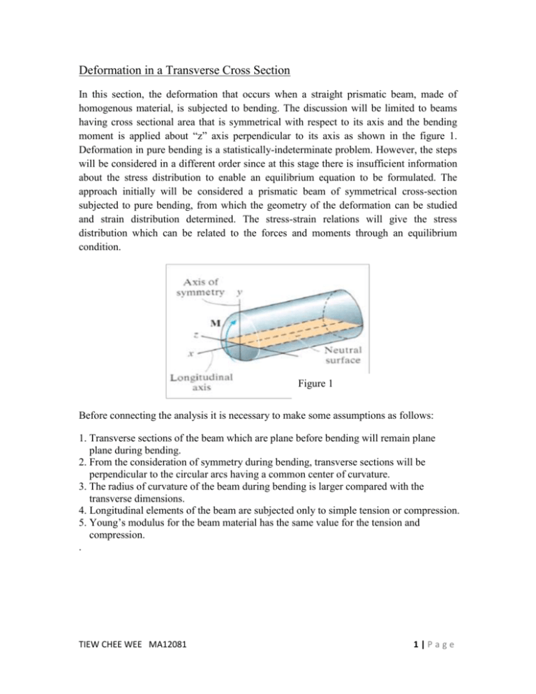
Deformation in a Transverse Cross Section In this section, the deformation that occurs when a straight prismatic beam, made of homogenous material, is subjected to bending. The discussion will be limited to beams having cross sectional area that is symmetrical with respect to its axis and the bending moment is applied about “z” axis perpendicular to its axis as shown in the figure 1. Deformation in pure bending is a statistically-indeterminate problem. However, the steps will be considered in a different order since at this stage there is insufficient information about the stress distribution to enable an equilibrium equation to be formulated. The approach initially will be considered a prismatic beam of symmetrical cross-section subjected to pure bending, from which the geometry of the deformation can be studied and strain distribution determined. The stress-strain relations will give the stress distribution which can be related to the forces and moments through an equilibrium condition. Figure 1 Before connecting the analysis it is necessary to make some assumptions as follows: 1. Transverse sections of the beam which are plane before bending will remain plane plane during bending. 2. From the consideration of symmetry during bending, transverse sections will be perpendicular to the circular arcs having a common center of curvature. 3. The radius of curvature of the beam during bending is larger compared with the transverse dimensions. 4. Longitudinal elements of the beam are subjected only to simple tension or compression. 5. Young’s modulus for the beam material has the same value for the tension and compression. . TIEW CHEE WEE MA12081 1|Page Figure 2 By using a highly deformable material such as rubber, we can illustrate what happens when a straight prismatic member is subjected to a bending moment. Consider, for example, the undeformed bar which has a square cross section and is marked with a longitudinal and transverse grid lines. When a bending moment is applied, it tends to distort these lines into the pattern shown in figure 2. Notice that the longitudinal lines become curved and the vertical transverse lines remain straight and yet undergo a rotation. Figure 3 In order to show how this distortion will strain the material, we will isolate a small segment of the beam located a distance x along the beam’s length and having an undeformed thickness Δx. Notice that any line segment, Δx , located at the neutral surface, does not change its length, whereas any line segment Δs, located at the arbitrary distance y above the neutral surface, will contract and become Δs’ after deformation. By definition, the normal strain along Δs is determined, namely , Ɛx = lim Δs →0 Δs′ −Δs Δs TIEW CHEE WEE MA12081 2|Page (a) (b) Figure 4 The strain in term of location y of the segment and the radius of curvature 𝑝 of the longitudinal axis of the element axis of the element. Before deformation, Δ𝑠 = Δ𝑥, (figure 4 (a), after deformation Δ𝑥 has a radius of curvature 𝑝 with the center of curvature at point O’ , figure 4(b). Since Δθ defines the angle between the sides of the element, Δ𝑥 = Δ𝑠 = 𝑝Δ𝜃 . In the same manner, the deformed length of the Δ𝑠 become Δ𝑠 ′ = (p-y) Δ𝜃 , the following equation can be obtained. Ɛ=- 𝑦 𝑝 This important result indicate that the longitudinal normal strain of any element within the beam depends on its location y on the cross section and the radius of the curvature of the beam’s longitudinal normal strain will vary linearly within y from the neutral axis. A contraction ( - Ɛ ) will occur in fibers located above the neutral axis ( + y), whereas elongation ( + Ɛ ) will occur in fibers below the axis ( - y). The variation in strain over the cross section is shown in the figure 5. Ɛ=-( 𝑦 𝑐 )Ɛ max y Δ𝑥 TIEW CHEE WEE MA12081 Figure 5 : Normal strain distribution 3|Page Here the maximum strain occurs at the outermost fiber, located a distance of y = c from 𝑦 the neutral axis. Applying Ɛ = , since Ɛ max = c / 𝑝 , then by division 𝑝 Ɛ Ɛ max =-( 𝑦/𝑝 𝑐/𝑝 ) so that, Ɛ=-( 𝑦 𝑐 ) Ɛ max This normal strain depends only on the assumption made regards to the deformation. When a moment is applied to the beam, therefore, it will only cause a normal stress in the longitudinal or x- direction. All the other components of normal and shear stress will be zero. It is uniaxial state of stress that cause material to have longitudinal normal strain component Ɛ max . Furthermore, by Poisson’ ratio, there must also be associated strain components Ɛ y = - v Ɛ x and Ɛ z = - v Ɛ x , which deform the plane of cross-sectional area, although these deformation is usually neglected. Such deformation will, however, cause the cross-sectional dimensions to become smaller below the neutral axis and larger above the neutral axis. The illustration of it can be seen in figure Figure 6 Consideration of the beam subjected to pure bending shown in Figure indicates that the lower surface stretches and is therefore in tension and the upper surface shorten and thus is in compression. Hence there must be an xz-plane in between in which longitudinal deformation is zero. This is termed the neutral plane, and a transverse axis lying in the neutral plane is the neutral axis. Consider the deformations between two sections AC and BD , a distance δx apart, of an initially straight beam. A longitudinal EF at the distance y below the neutral axis will have initially the same length as the GH at the neutral axis. During bending EF stretches to become E’F’ but GH being at the neutral axis is unstrained when it become G’H’. Therefore, if R is the radius curvature of G’H’, TIEW CHEE WEE MA12081 4|Page G’H’ = GH = δx = R δ θ E’F’ = ( R + y ) δ θ and the longitudinal strain in fibre E’F’ is 𝐸 ′ 𝐹′ −𝐸𝐹 Ɛx = 𝐸𝐹 but EF = GH = G’H’ = R δ θ ; therefore Ɛx = ( R + y ) δ θ −( R ) δ θ (R )δθ Hence, 𝑦 Ɛx = 𝑅 and since R= dx / d θ , therefore also 𝑑θ Ɛx = 𝑦 𝑑𝑥 Figure 7 Regarding deformation in the y- and z- directions, it is apparent that the changes in the length of the beam will result in changes in the transverse dimensions. For example, the fibers in compression will be associated with an increase in thickness, whereas the region in tension will show a decrease in beam thickness. The transverse strains will be σx Ɛz = Ɛy = - 𝑉σx 𝐸 = - VƐx and a beam of initially rectangular cross-section will take up the shape shown in Figure . This can be easily demonstrated by bending an eraser. The neutral surface, instead of being plane, will be curved. This behavior is termed anticlastic curvature. The deformations are extremely small and do not affect the solution for the longitudinal strains. Figure 8 TIEW CHEE WEE MA12081 5|Page Figure 9 Anticlastic curvature = 1 𝑣 𝑝 𝑝 ′= The relation obtained show that the elements located above the neutral surface ( y > 0 ), will expand in both the y and z direction, while the elements located below the neutral surface ( y < 0 ) will contract. In the case of a member of a rectangle cross section, the expansion and contraction of various elements in the vertical direction will compensate, and no change in the vertical dimension of cross section will be observed. As concerned, however, the expansion of the elements located above the neutral surface and the corresponding contraction of the elements located below that surface will result in the various horizontal lines in section being bent into arcs of circle. The situation observed here is similar to that observed earlier in a longitudinal cross section. We can conclude that the neutral axis of transverse section will be bent into a circle of radius 𝑝’ = 𝑝/v. Note : The radius of curvature , ρ , captures the intensity with which a segment of a beam has deformed in bending and ρ is defined as the radius of circle into which a longitudinal line of the initially straight beam has deformed. The reciprocal , K = 1/ ρ , is referred to as the curvature. In conclusion , the section of study can be sum up by a brief table below. Stress Produced by Each Load Individually TIEW CHEE WEE MA12081 Stress Distributions Stresses 6|Page
