You will analyze a shearing problem with hand calculations and with
advertisement
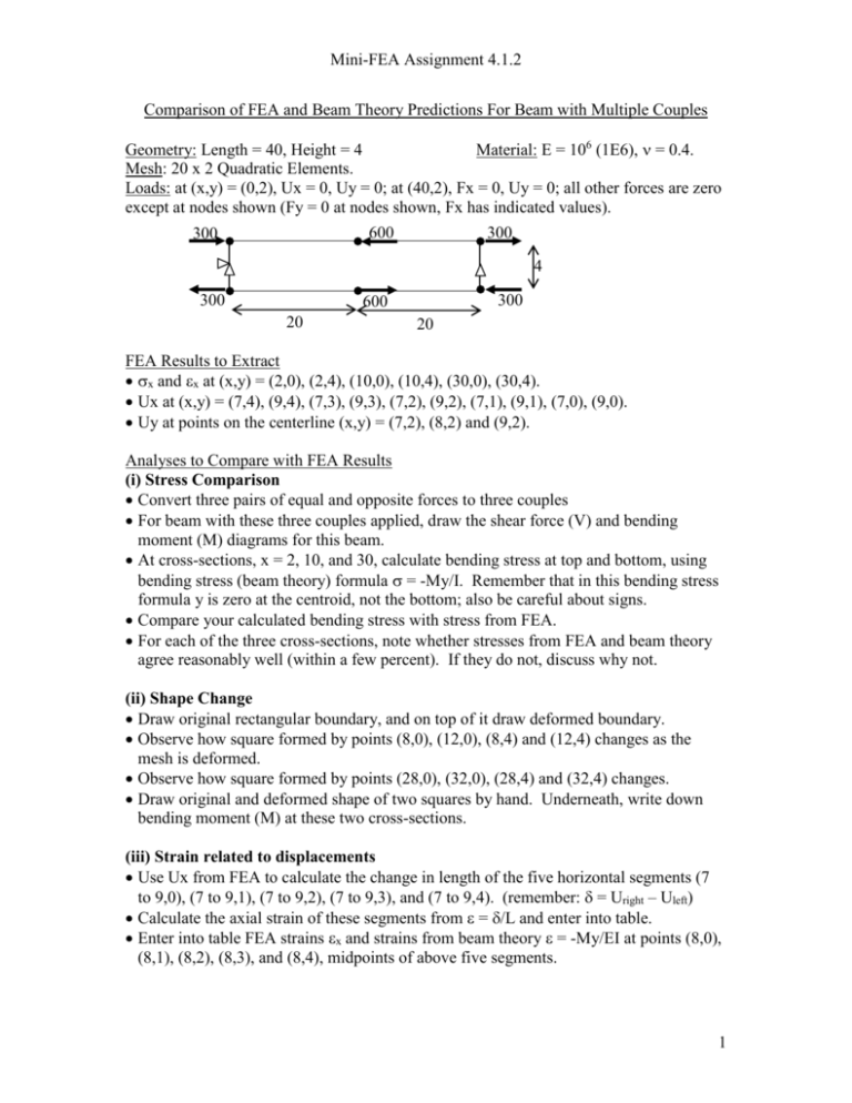
Mini-FEA Assignment 4.1.2 Comparison of FEA and Beam Theory Predictions For Beam with Multiple Couples Geometry: Length = 40, Height = 4 Material: E = 106 (1E6), = 0.4. Mesh: 20 x 2 Quadratic Elements. Loads: at (x,y) = (0,2), Ux = 0, Uy = 0; at (40,2), Fx = 0, Uy = 0; all other forces are zero except at nodes shown (Fy = 0 at nodes shown, Fx has indicated values). 600 300 300 4 300 300 600 20 20 FEA Results to Extract x and x at (x,y) = (2,0), (2,4), (10,0), (10,4), (30,0), (30,4). Ux at (x,y) = (7,4), (9,4), (7,3), (9,3), (7,2), (9,2), (7,1), (9,1), (7,0), (9,0). Uy at points on the centerline (x,y) = (7,2), (8,2) and (9,2). Analyses to Compare with FEA Results (i) Stress Comparison Convert three pairs of equal and opposite forces to three couples For beam with these three couples applied, draw the shear force (V) and bending moment (M) diagrams for this beam. At cross-sections, x = 2, 10, and 30, calculate bending stress at top and bottom, using bending stress (beam theory) formula = -My/I. Remember that in this bending stress formula y is zero at the centroid, not the bottom; also be careful about signs. Compare your calculated bending stress with stress from FEA. For each of the three cross-sections, note whether stresses from FEA and beam theory agree reasonably well (within a few percent). If they do not, discuss why not. (ii) Shape Change Draw original rectangular boundary, and on top of it draw deformed boundary. Observe how square formed by points (8,0), (12,0), (8,4) and (12,4) changes as the mesh is deformed. Observe how square formed by points (28,0), (32,0), (28,4) and (32,4) changes. Draw original and deformed shape of two squares by hand. Underneath, write down bending moment (M) at these two cross-sections. (iii) Strain related to displacements Use Ux from FEA to calculate the change in length of the five horizontal segments (7 to 9,0), (7 to 9,1), (7 to 9,2), (7 to 9,3), and (7 to 9,4). (remember: = Uright – Uleft) Calculate the axial strain of these segments from = /L and enter into table. Enter into table FEA strains x and strains from beam theory = -My/EI at points (8,0), (8,1), (8,2), (8,3), and (8,4), midpoints of above five segments. 1 Mini-FEA Assignment 4.1.2 (iv) Deflection, Slope, Curvature Estimate the slope of centerline at x = 7.5, using Uy/x, with Uy at (7,2) and (8,2). Estimate the slope of centerline at x = 8.5, using Uy/x, with Uy at (8,2) and (9,2). Estimate curvature, = d2Uy/dx2 from (slope)/x, using slopes at x = 8.5 and 9.5. Calculate M = EI, and compare this with bending moment M at x = 8 found earlier. 2 Mini-FEA Assignment 4.1.2 Results (i) Stress Comparison Draw body as a beam with loads. Underneath, draw V and M diagrams (watch signs). Show terms in calculation of stress from beam theory = -My/I. (2,0) (2,4) (10,0) (10,4) (30,0) (30,4) x (FEA) x (Beam) Comment on stress comparison: 3 Mini-FEA Assignment 4.1.2 (ii) Shape Change Draw original shape of rectangular boundary. Draw on top of it the shape of the boundary when the body is deformed. Draw original shape of two squares then as they are deformed. Write down bending moment (with sign) underneath each. (iii) Strain related to displacements (7,4) (9,4) (7,3) (9,3) (7,2) (9,2) (7,1) (9,1) (7,0) (9,0) Ux (8,4) (8,3) (8,2) (8,1) (8,0) x (/L) x (FEA) x (Beam) (iv) Deflection, Slope, Curvature (7,2) (8,2) (9,2) Uy (7.5,2) (8.5,2) Slope (= Uy/x) = (Slope)/x M = EI M (from bending) At x = 8 4
