Optical Processing: 4F System & Spatial Filtering Lab
advertisement
ECE184
4F OPTICAL PROCESSING SYSTEM
OBJECTIVE
To study optical processing of space-invariant system to perform coherent spatial filtering in a)
positive real domain, and b) complex domain.
BACKGROUND
According to the Abbe theory of image formation an object, illuminated by a plane wave,
forms diffraction pattern in the focal plane of a lens (or in "Fourier transform plane" if consider
a lens as performing FT operation). A perfect image of the object can only be formed when all
diffracted orders (or spatial frequencies) are allowed to pass through the optical system.
A linear space-invariant system is completely specified by its impulse response. The
impulse response depends only on coordinate difference between input and output planes. This
input-output relationship is expressed mathematically as convolution. With coherent
illumination, a space-invariant imaging system is linear in complex amplitude. The output image
amplitude is the amplitude convolution of the object and Fourier transform of the exit pupil
function (impulse response).
A. Coherent Positive Real Spatial Filtering
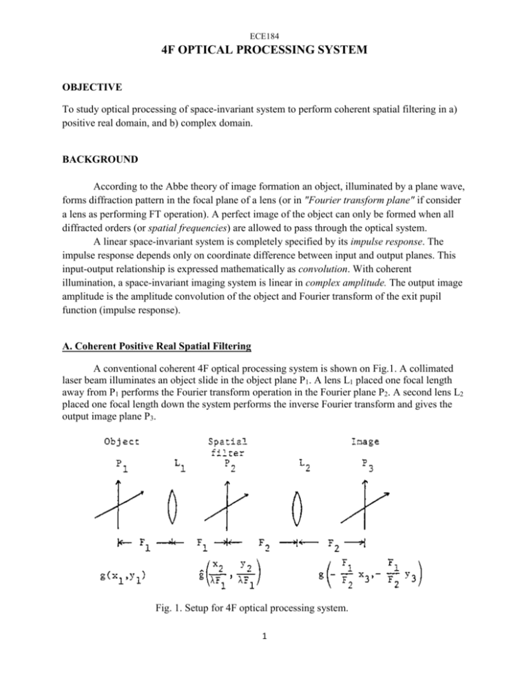
A conventional coherent 4F optical processing system is shown on Fig.1. A collimated
laser beam illuminates an object slide in the object plane P1. A lens L1 placed one focal length
away from P1 performs the Fourier transform operation in the Fourier plane P2. A second lens L2
placed one focal length down the system performs the inverse Fourier transform and gives the
output image plane P3.
Fig. 1. Setup for 4F optical processing system.
1
1. Fourier Plane Filtering.
Using simple positive real spatial filters in the Fourier plane of the system in Fig.1, the
spatial frequency spectrum of input image can be modified to obtain filtered output image.
At the object plane P1 we have transmittance function g(x1, x2). Lens L1 forms the Fourier
transform of the object at the plane P2. The amplitude distribution at P2 becomes
where ĝ = F{g}is the Fourier transform of g , and c1 is complex constant. Lens L2 forms the
Fourier transform of the field at P2 in the image plane P3. The amplitude distribution at P3 can be
expressed as
If we insert a filter at P2 which has an amplitude transmittance
then the amplitude distribution just behind the filter plane is proportional to the product ĝĥ, and
lens L2 transforms this amplitude distribution into the image plane P3. The amplitude distribution
at P3 can be expressed as
where h = F - 1{h}, and the intensity distribution is
and C = │c1c2 │2.
If the object is a point source g(x1, x2) = δ(x1, x2), the image amplitude will be c1c2h, and
the impulse response of the optical system is h if we neglect the constant. Hence, by inserting a
spatial filter at P2 we can control the impulse response and modulate the final image.
In the lab the following filter will be studied.
a) High-pass filter
2
The low spatial frequency components of an input object can be removed by placing an
obstruction in the transform plane that will block the area around the DC component. The
transparent area elsewhere permits all light corresponding to spatial frequencies greater than a
specific value to pass through the lens L2.
b) Low-pass filter
A low-pass filter can be formed by putting an iris in the transform plane. This iris will
permit all light corresponding to spatial frequencies below a specific value to pass through the
lens L2.
c) Band-pass filter
A band-pass filter can be constructed to permit light corresponding to a specific range of
spatial frequencies to pass through the lens L2. The band-pass filter can be made by combining a
high-pass filter with a low-pass filter.
2. Sampling and Recovery.
The same optical system studied so far can be used to perform recovery of a sampled
image. Consider the bandlimited function f(x) whose Fourier transform f(υx) = 0 for
│ υx │≥w/2. The sampled version of f(x) is
3
The spectrum of fs(x) is given by
where υs = 1/ xs is the sampling rate. We can see that as long as υs ≥ w, the various spectra of ̂ f^s
will not overlap. Then by applying the sampled function fs(x) as the input to a low-pass filter,
and by selecting the cutoff frequency of the filter to satisfy the inequality w/2 ≤ υ c ≤ (υs - w/2),
the spectrum of the bandlimited function f(x) will be recovered
where it should be noted that
Consequently, the output itself is
Except for an unimportant multiplicative constant, the original function has been recovered
exactly.
4
EXPERIMENTS
A. Coherent Positive Real Spatial Filtering
1. Set up the optical processing system as shown in Fig.1 to demonstrate the Abbbe-Porter
experiment. The object is crossed grating. The spatial filters used are an iris, and a slit that can be
rotated.
- Show the effect of iris size on the output;
- Show the effect of slit orientation on the output. Consider at least the following three slit
positions:
2. Use the same optical processing system to perform low-pass spatial filtering and high-pass
spatial filtering.
- Use letter "A" as an object.
-What is the effect of blocking only the DC portion of the Fourier transform in the filter plane?
-What is the effect of the following filters: double-sided high-pass (1D), single-sided high-pass
(1D), band-pass (2D), low-pass filter (2D).
- What is the visual effect of misfocusing (i.e. adjusting the camera position away from
the image plane) when an image is high-passed and when it is low-passed?
3. Use the same optical system to perform the interpolation operation necessary to convert a
sampled image into a continuous one.
- Use an image sampled in two directions (letter "A" and a 2D-grating).
- Use an image sampled in one direction (raster sampling) to perform raster line removal (letter
"A" and a 1D-grating).
5


