Bally/Williams Pre-95 Smart Color Installation
advertisement
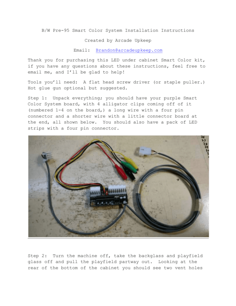
B/W Pre-95 Smart Color System Installation Instructions Created by Arcade Upkeep Email: Brandon@arcadeupkeep.com Thank you for purchasing this LED under cabinet Smart Color kit, if you have any questions about these instructions, feel free to email me, and I’ll be glad to help! Tools you’ll need: A flat head screw driver (or staple puller.) Hot glue gun optional but suggested. Step 1: Unpack everything; you should have your purple Smart Color System board, with 4 alligator clips coming off of it (numbered 1-4 on the board,) a long wire with a four pin connector and a shorter wire with a little connector board at the end, all shown below. You should also have a pack of LED strips with a four pin connector. Step 2: Turn the machine off, take the backglass and playfield glass off and pull the playfield partway out. Looking at the rear of the bottom of the cabinet you should see two vent holes with grating over them; remove the staples holding down the grate on the left hole. Step 3: Starting with the entire kit in the head of the game, run the 4 pin connector down through the body of the game and carefully push it through the hole you just removed the grate from, see pic below. Step 4: Just to familiarize yourself with the connectors in this kit, you should see a 9 pin female connector, a 5 pin female connector and their male counterparts coming off the purple board. The chip and dipswitch should face up when the board is plugged in. Find the connectors J124 and J125 on the lower middle of the power board in the backbox of your game. Step 5: down. Unplug the connectors J124 and J125 and let them hang Now plug the female connectors of the purple board to the male plugs on the games board, it may be hard to push on, that’s normal. Then plug the games female plugs down onto the purple board. The connectors should be keyed to only plug into the correct places. Depending on your game it may be easier to reverse that order, plug the games female connectors onto the purple board then plug it into the games board. Step 6: Next we will connect the alligator clips to the game. If you look just above and to the right of the connectors we just used you should see a bunch of transistors with metal tabs sticking out. These are labeled on the computer board, look for “Q1” or “Q50” or so on, you should have received an email from me stating which transistors each clip goes to for your game (it changes game to game. Clip the alligator clip right on the metal tab. If your kit requires the clips to go on one of the auxiliary driver boards further away you should have been supplied with extension cables, if you weren’t and need them please contact me and they will be sent right out free of charge. Step 7: The next step is to connect the little 4 pin connector board to the game. Locate J116, J117 and J118 in the lower left of the same power board. This little connector board will plug into any of those. Pick whichever one seems easiest to you, especially if one isn’t used in your game. Use the same process with this board, unplug the connector, plug the kits connector onto the board then plug the games connector onto the kit. You should now have everything in the backbox connected and it should look like the pic below (with your alligator clips connected as well.) Step 8: The only thing left is sticking the LED strips to your game. There are two sections. One is just a straight piece; the other is an "L" shape. They will go around the front 3 edges of the cabinet. You can peel the backing off the LED strips and attach the "L" piece first to the side and the front then finish up with the other side piece. (This allows for it to be installed on either standard or wide body games.) The strips have an adhesive backing, you just need to peel the back off and stick them to the game. See pic below. NOTE: Depending on your machine and the adhesives on the LED strips they may not stick as well as they should. In that case a few shots from a hot glue gun will definitely hold them in place. It just seems to depend on the game. You can also use the hot glue to hold the wires in place as well. Step 9: Plug the LEDs four pin connector into the kits four pin connector you put through the grate earlier then tuck any extra wire back up into the game. That should be it for the installation! Put the game back together, checking to be sure no electrical components from the game touch the Smart Board, and turn it on! Step 10: The little red switch on the board between the connectors is for you to change the “attract mode” lights if you decide you don’t like them as they are. Some kits will remove the attract mode lights all together in others it will provide a less active version if you find the changing colors in attract mode too busy for your liking. Just flip it on or off at any time, but note the board may need to be restarted for the change to take effect. Also note that while connecting the alligator clip to the wrong tab won’t damage the game or the kit it may cause the kit to not work properly. So if it doesn’t seem to be working correctly, especially if the attract mode lights aren’t working properly, double check the clip is on the correct tab. If you have any questions on any step of the way, or you have an idea to improve this kit or the instructions, send me an email at Brandon@arcadeupkeep.com Kit and Instructions by Arcade Upkeep. www.arcadeupkeep.com P.S. The performance of this kit was designed to be adjustable to your specifications through a simple chip swap so if you see anything you don’t like or would like changed in any way, NEVER hesitate to contact us!
