VCXO = 491.52MHz PRI_REF= 100 MHz Frequency (VCXO_IN or
advertisement

VCXO = 491.52MHz
PRI_REF= 100 MHz
Frequency (VCXO_IN or AUX_IN) / Frequency (PRI_REF or SEC_REF) = (P*N)/(R*M)
The VC(X)O_IN clock operates up to 1.5GHz through the selection of external VC(X)O and loop filter
components. The PLL loop bandwidth and damping factor can be adjusted to meet different system
requirements.
The CDCE72010 can lock to one of two reference clock inputs (PRI_REF and SEC_REF) and supports
frequency hold-over mode for fail-safe and system redundancy. The outputs of the CDCE72010 are user
definable and can be any combination of up to 10 LVPECL/LVDS outputs or up to 20 LVCMOS outputs. The
built-in synchronization latches ensure that all outputs are synchronized for very low output skew.
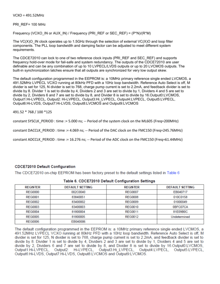
The default configuration programmed in the EEPROM is: a 10MHz primary reference single ended LVCMOS, a
491.52MHz LVPECL VCXO running at 80kHz PFD with a 10Hz loop bandwidth. Reference Auto Select is off, M
divider is set for 125, N divider is set to 768, charge pump current is set to 2.2mA, and feedback divider is set to
divide by 8. Divider 1 is set to divide by 4, Dividers 2 and 3 are set to divide by 1, Dividers 4 and 5 are set to
divide by 2, Dividers 6 and 7 are set to divide by 8, and Divider 8 is set to divide by 16.Output0:LVCMOS,
Output1:Hi-LVPECL, Output2: Hi-LVPECL, Output3:Hi_LVPECL, Output4:LVPECL, Output5:LVPECL,
Output6:Hi-LVDS, Output7:Hi-LVDS, Output8:LVCMOS and Output9:LVCMOS
491.52 * 768 / 100 *125
constant SYSCLK_PERIOD : time := 5.000 ns; -- Period of the system clock on the ML605 (Freq=200MHz)
constant DACCLK_PERIOD : time := 4.069 ns; -- Period of the DAC clock on the FMC150 (Freq=245.76MHz)
constant ADCCLK_PERIOD : time := 16.276 ns; -- Period of the ADC clock on the FMC150 (Freq=61.44MHz)
; Values are specified in hexadecimal format:
; 28 MSB = data, 4 LSB = address.
REGISTER
DEFAULT
FMC150 Setting
FMC150 Setting
FMC150 Setting
cdce72010_init_int_491_52MHz.coe cdce72010_init_ext_491_52MHz.coe cdce72010_init_int_737_28MHz.coe
SETTING
REG0000
002C0040
683C0350
683C0310
683C0350
REG0001
83840051
68000021
68000021
68000021
REG0002
83400002
83040002
83040002
830A0002
REG0003
83400003
68000003
68000003
68000003
REG0004
81800004
E9800004
E9800004
E9820004
REG0005
81800005
68000005
68000005
68000005
REG0006
EB040006
68000006
68000006
68000006
REG0007
EB040717
83800017
83800017
83820017
REG0008
010C0158
68000098
68000098
68000098
REG0009
01000049
68050CC9
68050CC9
68050CC9
REG0010
0BFC07CA
05FC270A
05FC270A
08FC270A
REG0011
81E09B0C
0000040B
0280044B
0000040B
REG0012 Undetermined 0000180C
0000180C
0000180C
Register 2 Address 0x01: SPI Mode - Table 8; FOR REGISTER 1 TO 8 BITS {19[BIT6] TO 13[BIT0]} FOR REGISTER 11 BITS
{11[BIT6] TO 5[BIT0]}
Output 2; Reg 2: Divide By == 04h & Ah ==0000 010 & 0000 101 == 8 & 12
Output 4; Reg 4: Divide By == 80h & 82h ==1000 000x & 1000 001x == 8 & 12
Output 7; Reg 7: Divide By == 80h & 82h ==1000 000x & 1000 001x == 2 & 3
FB Path Ctrl; Reg 11; Divide By == 04h & 04h ==0000 010x & 0000 010x == 8 & 8
FB_DIS; Reg 11, bit 2; When set to 0, FB divider is active; 1 disabled (disabled on internal)
Reg 11, bits 21,19; xx0x 0xxx & xx1x 1xxx;
bit 21 OUT_MUX_SEL Set to 0 it selects the VCXO Clock and if Set to 1 it selects the AUX Clock; (AUX for external)
bit 19 PD_PLL; set to 0, PLL is in normal mode; 1 powered down (down for external)
REG0010; bit 27 … 14 == VCXO Divider N Bit 13 … 0; 05FC & 08FC == 0000 0101 1111 11xx & 0000 1000 1111 11xx ==
adjust 00 0001 0111 1111 &00 0010 0011 1111 == 17F & 23F == 383 & 575.
REG0010; bit 13 … 0 == Reference Divider M Bit 13 … 0; 270h == 624
What are you using to monitor the input and output waves?
Have you made any iDelay adjustments on your inputs?
For the supplied reference designs, the sampling frequency of the FMC150 ADC and DAC are determined by the
CDCE72010 clock outputs U2 and U7, respectively. The ADC then provides the FPGA with CLK_AB for IO SerDes sampling
clock via the MMCM. A block diagram of this is found in the “Virtex-6 DSP Kit with High-Speed Analog - Getting Started
Guide” pdf.
Cdce72010_ctl.vhd initializes the internal registers in the CDCE72010 from FPGA ROM via SPI. FPGA ROM is built with
CORE Generator’s Block Memory Generator, using cdce72010_init_int_491_52MHz.coe. ADC and DAC initialization
follow the same procedure, using respective .coe files. i.e.
;******************************************************************
;** CECE72010 Initialization
**
;******************************************************************
;** The register settings allows the clock signals derived from **
;** an onboard 491.52MHz VCXO
**
;******************************************************************
;
; This .COE file specifies initialization values for a block
; memory of depth=16, and width=32.
; Values are specified in hexadecimal format:
; 28 MSB = data, 4 LSB = address.
;
; Loading from ROM stops when address 0xC has been processed.
; therefore this register must be the last entry in this file.
;
memory_initialization_radix=16;
memory_initialization_vector=
683C0350,
68000021,
83040002,
68000003,
E9800004,
68000005,
68000006,
83800017,
68000098,
68050CC9,
05FC270A,
0000040B,
0000180C;
Before re-building, once necessary initialization file changes, and mmcm_adac Clock Wizzard changes to support these
different frequencies are made, you need to ensure changes to clock constraints in “ml605_fmc150.ucf” are also made.


