High Refractive Index Thermally Stable Silicones Based on
advertisement
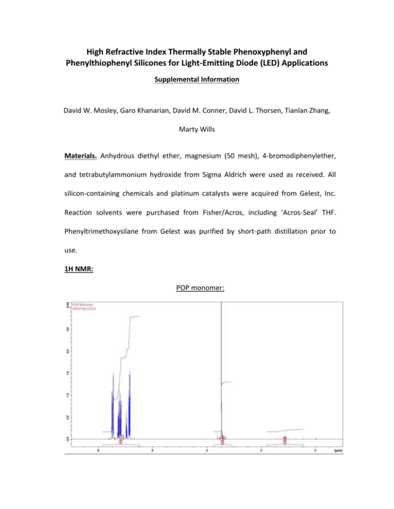
High Refractive Index Thermally Stable Phenoxyphenyl and Phenylthiophenyl Silicones for Light-Emitting Diode (LED) Applications Supplemental Information David W. Mosley, Garo Khanarian, David M. Conner, David L. Thorsen, Tianlan Zhang, Marty Wills Materials. Anhydrous diethyl ether, magnesium (50 mesh), 4-bromodiphenylether, and tetrabutylammonium hydroxide from Sigma Aldrich were used as received. All silicon-containing chemicals and platinum catalysts were acquired from Gelest, Inc. Reaction solvents were purchased from Fisher/Acros, including ‘Acros-Seal’ THF. Phenyltrimethoxysilane from Gelest was purified by short-path distillation prior to use. 1H NMR: POP monomer: PSP monomer: Vinyl A: Hydride A: Calculation of refractive index of silicones A graph of the calculated versus measured refractive indices for compounds in this paper is shown in Figure 1. 0.7 nexp -1 0.6 0.5 Equation y = a + b*x Weight No Weighting Residual Sum of Squares 0.00116 Pearson's r 0.98473 0.96463 Adj. R-Square 0.4 Standard Error Value 0.4 B Intercept B Slope 0.5 ncalc -1 -0.02907 0.04349 1.06717 0.07703 0.6 Figure 1. Graph of nexp -1 vs. ncalc-1 showing the expected linear relationship. The linear regression analysis is shown as well. Choice of TBAH as Synthesis Catalyst When using a base-catalyzed condensation reaction with phenyl-containing monomers, it is expected that cyclic phenylcyclosiloxanes may form, based on both the catalyst type and the monomers involved. In particular diphenyl D monomers are known to readily form insoluble hexaphenyltricyclosiloxane and octaphenyltetracyclosiloxane when polymerized under basic conditions, due to the thermodynamic stability of the cyclosiloxanes 1. Therefore, catalyst screening was done to minimize this known reaction using a model condensation reaction*. For a set monomer mixture containing 59% diphenyldimethoxysilane, 33% phenylmethyldimethoxysilane, and 8% divinyltetramethyldisiloxane, numerous catalysts were screened. It was assumed that a low MW peak in the GPC represented cyclic diphenylsiloxanes. Based on this screening, tetrabutylammonium hydroxide gave the best combination of polymerization rate, ease of handling, and a presumed low cyclics formation. The assumption that the low MW peak represents cyclic siloxanes is justified based on the MALDI-MS information presented for Vinyl A and Vinyl C, as well as MALDI analysis of diphenylsiloxane polymerizations without POP or PSP. Our empirical observations of white solid formation or haze also correspond with the assumption that for the monomer mixture above, the low molecular weight fraction is predominantly cyclic diphenylsiloxanes and * Barium hydroxide is a known basic catalyst that results in low cyclic siloxane formation, as disclosed in US5109094. hence forms insoluble species. However, it should be pointed out that high molecular weight cyclic siloxanes are very difficult to rule out as well2. Compound Zinc acetate Zinc carbonate Zinc oxide/hydroxide Barium hydroxide Barium sulfate Barium acetate Barium carbonate Barium carbonate and ammonium hydroxide Calcium carbonate Calcium hydroxide Calcium phosphate Calcium acetate Magnesium hydroxide Lanthanum oxide Tetramethylammoniumhydroxide Copper acetate Tetraethylammonium hydroxide Tetrabutylammonium hydroxide (TBAH) Tetrabutylammonium hydroxide (TBAH) DMAP BisDMAP Trioctylamine Guanidine Ethanolamine Tris(2-aminoethyl)amine Cesium hydroxide Potassium hydroxide 1:1 Tetramethylguanidine/sulfuric acid 1:1 Tetramethylguanidine/trifluorome thanesulfonic acid n-Hexyl amine t-Butyl amine Catalyst Mol% %Cyclics by GPC 2.2 3.6 2.1 2.4 2.8 1.7 NR NR NR 8.4% NR NR NR NR - cyclics by TLC NR 100.0% 100.0% NR minimal reaction minimal reaction Slight rxn 100.0% 33.0% 4.3 5.8 2.4 3 7.5 1.9 1.2 2.4 1.7 1.1 5 3.9 1.6 1.3 4.2 10.6 4.1 3.3 7.7 21.0% 1hr@110=32% 2hr@110=27% 41.0% NR NR 37.0% 38.0% 100.0% 69.4% 63.6% 2.2 25.2% 2.9 4.7 7.4 30.5% 35.0% 25.0% Table 1. Catalyst screening study for selection of a siloxane condensation catalyst that gives as few cyclic siloxanes as possible. SEC-MALDI Analysis: SEC system: Column: Eluent: Flow rate: Detection: Agilent 1100 2 X PLgel 5µ Mixed-D (300 x 8 mm ID) with 5µ guard Tetrahydrofuran 1.0 mL/min RI @ 40oC Injected volume of sample solution: 100 µL. MALDI-TOF mass spectra were acquired on a Bruker Daltonics Ultraflex instrument equipped with a nitrogen laser (=337 nm). In the experiment, 20 mg of DHB was dissolved in 1 mL of THF as MALDI matrix solution and NaI was added into matrix solution to facilitate ionization. Each of 0.5 mL SEC fractions was concentrated to ~50 µL. The fraction solution was premixed with matrix solution at a ratio of 1:10. 0.3 μL of the sample/matrix mixture was then placed on the sample target plate and was air dried for MALDI-MS analysis. 3000 907.2 Intens. [a.u.] To examine molecular composition, SEC fractions were collected and analyzed by MALDI mass spectrometry. The MALDI mass spectrum of the Vinyl A fraction at 13-13.5 mL is shown in Figure 2 for the lower MW region of the distribution. The spectrum mainly represents short chain, cyclic polysiloxanes. There is also a small amount of hydroxy terminated polysiloxane in the spectrum. The MALDI mass spectrum of the 10.5-11.0 mL fraction is shown in Figure 3 for the higher MW region of Vinyl A. Based on their masses, there are the two kinds of polymeric species in the mass spectrum of Figure 3: polysiloxanes capped by phenylmethylvinylsilyl at both ends as major components, and polysiloxanes capped by one phenylmethylvinylsilyl and one methoxy. A A 999.3 2500 2000 1500 B A 1381.4 1289.4 A 1019.3 976.2 927.3 1091.3 883.2 C C A 1197.3 819.2 791.1 A 805.1 500 A 1105.3 B 727.1 713.1 1000 0 700 800 900 1000 1100 1200 1300 1400 m/z Figure 2. MALDI mass spectrum analysis of Vinyl A SEC Fraction of 13.0-13.5 min. The letters indicate (A) short chain, cyclic polysiloxanes; (B) hydroxyl terminated polysiloxanes; (C) polysiloxanes capped by phenylmethylvinylsilyl at both ends. C C 2195.0 2088.0 C 1250 C 2286.1 1995.9 2181.0 D C 2485.2 2392.2 2247.0 D C C 2577.3 2170.0 2062.0 D 2155.0 500 C D D 1969.9 C 1903.9 750 C 1797.9 1000 2378.2 Intens. [a.u.] 1500 C 250 0 1800 2000 2200 2400 2600 2800 3000 m/z Figure 3. MALDI mass spectrum analysis of Vinyl A SEC Fraction of 10.5-11.0 mL. The letters indicate (C) polysiloxanes capped by phenylmethylvinylsilyl at both ends and (D) polysiloxanes capped by phenylmethylvinylsilyl at one end and methoxy at the other. Solvent Extraction of Crosslinked POP Formulations Formulations of Vinyl A with Hydride A in a 1:2 ratio of functional groups were crosslinked with Ossko catalyst at a level of 1 ppm platinum metal. Oligomers of Vinyl A but with different endgroups (as in Figure 3 of the paper) were treated in the same way. The crosslinked materials were soaked in toluene overnight after being broken up with a spatula. The toluene fraction was isolated and rotovaped to give a wt% extractable content. The results are summarized in Table 2. Additionally, the extracted material was examined on an Oligopore SEC column versus typical Vinyl A oligomers before extraction (Figure 4). The extracted material overlaps precisely with the incoming low molecular weight portion of Vinyl A. Endgroup Wt% Extractables Wt% Extractables Wt% Extractables 6 hr cure@130 C 6 hr cure@130 C and 16 hr@160 C 6 hr cure@130 C and 16 hr@160 C and 24 hr@ 200 C VinPhMeSi- 25% 28% 25% Vin2MeSi- 41% 39% 35% VinMe2Si- 28% 25% 21% Table 2. Solvent extraction of cured formulations with toluene. Figure 4. GPC of extractable study on an Oligopore™ column which resolves oligomers of Vinyl A. Shown are two batches of Vinyl A, along with extracted fractions for the three different cure times of formulated Vinyl A plus Hydride A. FTIR Cure Study FTIR data was gathered on a Mattson RS-1 FTIR. Formulations were prepared using Hydride A, 1 ppm of platinum catalyst (Ossko), and 2 equivalents of hydride versus one equivalent of vinyl. A few drops were placed between salt plates. The salt plates were cured in an oven for 30, 60, 120, 240, and 1200 minutes. The cure temperature was 130 oC for the first 4 hrs, and then the temperature was 160 oC for the final 16 hrs. The reduction in the Si-H stretch at 2128 cm-1 was followed as the formulations cured between salt plates. For all formulations, the reduction in Si-H was normalized versus the C-C aryl stretch at 1600 cm-1, which is expected to remain constant during the cure process. UV-Vis Characterization Ocean Optics Heat Aging data. Spectra were acquired using an Ocean Optics USB 4000 spectrophotometer with a tungsten light source and an Ocean Optics integrating sphere accessory. Data were adjacent averaged over 7 points. Spectral artifacts at 611.66614.27 nm; 435.8-437.71 nm; and 405.18-406.15 nm were removed from several of the curves. Refractive Index Measurements Refractive indices on films were measured with a Metricon 2010 instrument (Pennington , NJ) . Refractive indices of liquid oligomers were measured with a Reichert Abbe Mark II refractometer. LED Testing Method The system is shown below. A heated water flask was used to maintain the relative humidity at ~50% during temperature cycling. Temperature inside the box was cycled from -10 oC to 85 oC every 12 hrs with relative humidity inside the box kept at 50%. The LEDs were powered at 1 amp forward bias for the duration of the test. A track carried an optical detector (Ocean Optics) that moved along and measured the light output in lumens from each LED and recorded it periodically. About 50% of the repackaged devices failed to produce good quality light output for further testing due to various problems such as air bubble formation or wire bond breakage, problems which are not unexpected when reusing a previously made device.

