here
advertisement

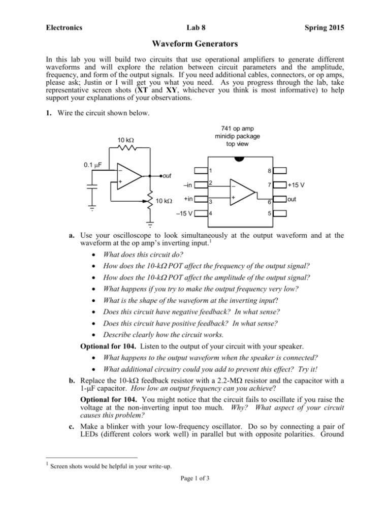
Electronics Lab 8 Spring 2015 Waveform Generators In this lab you will build two circuits that use operational amplifiers to generate different waveforms and will explore the relation between circuit parameters and the amplitude, frequency, and form of the output signals. If you need additional cables, connectors, or op amps, please ask; Justin or I will get you what you need. As you progress through the lab, take representative screen shots (XT and XY, whichever you think is most informative) to help support your explanations of your observations. 1. Wire the circuit shown below. 741 op amp minidip package top view 10 k 0.1 F – 1 out + 10 k –in 2 +in 3 –15 V 4 8 – + 7 +15 V 6 out 5 a. Use your oscilloscope to look simultaneously at the output waveform and at the waveform at the op amp’s inverting input.1 What does this circuit do? How does the 10-k POT affect the frequency of the output signal? How does the 10-k POT affect the amplitude of the output signal? What happens if you try to make the output frequency very low? What is the shape of the waveform at the inverting input? Does this circuit have negative feedback? In what sense? Does this circuit have positive feedback? In what sense? Describe clearly how the circuit works. Optional for 104. Listen to the output of your circuit with your speaker. What happens to the output waveform when the speaker is connected? What additional circuitry could you add to prevent this effect? Try it! b. Replace the 10-k feedback resistor with a 2.2-M resistor and the capacitor with a 1-F capacitor. How low an output frequency can you achieve? Optional for 104. You might notice that the circuit fails to oscillate if you raise the voltage at the non-inverting input too much. Why? What aspect of your circuit causes this problem? c. Make a blinker with your low-frequency oscillator. Do so by connecting a pair of LEDs (different colors work well) in parallel but with opposite polarities. Ground 1 Screen shots would be helpful in your write-up. Page 1 of 3 Electronics Lab 8 Spring 2015 one side of the combination, and connect the other side through a 330- resistor to the output of your circuit. 2. Wire circuit shown below using 741 op amps. 0.1 F out 2 10 k – + – – + + out 1 10 k Look at “out 1” and “out 2” with your oscilloscope.2 Study the effect of varying the 10-k POT. Explain how the circuit works. Why, in contrast to the circuit of part (1), does this circuit produce a nearly perfect triangle waveform? Why is it OK that the rightmost op amp has no input or feedback resistor? What’s the purpose of this op amp? Optional for 104. Note that the 10-k POT affects both the frequency and the amplitude of the triangle wave. Design a modification of the circuit so the triangle has fixed amplitude but variable frequency, and verify that the modified circuit works.3 Optional for 104 and 114. Design a modification that produces an asymmetric triangle, with different rise and fall times. Verify that your modification works.4 a. b. c. 3. Write-up. 1.a. What does this circuit do? How does the 10-kΩ POT affect the frequency of the output signal? How does the 10-kΩ POT affect the amplitude of the output signal? What happens if you try to make the output frequency very low? What is the shape of the waveform at the inverting input? Does this circuit have negative feedback? In what sense? Does this circuit have positive feedback? In what sense? 2 Screen shots would be helpful in your write-up. Screen shots would be helpful in your write-up. 4 Screen shots would be helpful in your write-up. 3 Page 2 of 3 Electronics Lab 8 Spring 2015 Describe clearly how the circuit works. Optional for 104. What happens to the output waveform when the speaker is connected? What additional circuitry could you add to prevent this effect? Explain your thinking. Try it! Did it work? 1.b. How low an output frequency can you achieve? Optional for 104. If the circuit failed to oscillate when you raised the voltage at the non-inverting input too much, explain why? What aspect of your circuit caused this problem? 2.a. Explain how this circuit works. Why, in contrast to the circuit of part 1, does this circuit produce a nearly perfect triangle waveform? Why is it OK that the rightmost op amp has no input or feedback resistor? What’s the purpose of this op amp? 2.b. Optional for 104. Design a modification of this circuit so the triangle has fixed amplitude but variable frequency. Explain your thinking and your approach. Did it work? 2.c. Optional for 104 and 114. Design a modification that produces an asymmetric triangle, with different rise and fall times. Explain your thinking and your approach. Did it work? Page 3 of 3


