Laser Scanner LaboratoryPage of 4Mohsen Alizadehfard
advertisement
MMAN3210
Engineering Experimentation
Laser Scanner Laboratory
Laboratory Exercise 3: Semester 2 2010
Mohsen Alizadehfard
Z3308893
Part 1: focusing on estimating the accuracy of the sensor, particularly the
random errors in the measurement
1.1 Approach
1.1.1 Test conditions
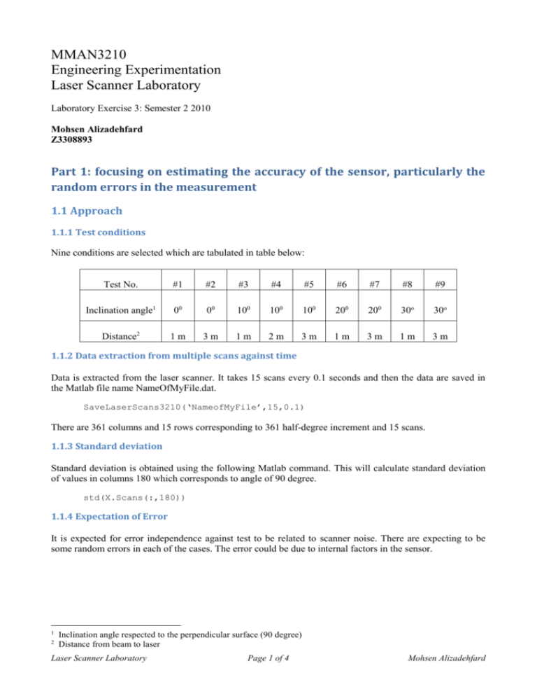
Nine conditions are selected which are tabulated in table below:
Test No.
#1
#2
#3
#4
#5
#6
#7
#8
#9
Inclination angle1
00
00
100
100
100
200
200
30o
30o
Distance2
1m
3m
1m
2m
3m
1m
3m
1m
3m
1.1.2 Data extraction from multiple scans against time
Data is extracted from the laser scanner. It takes 15 scans every 0.1 seconds and then the data are saved in
the Matlab file name NameOfMyFile.dat.
SaveLaserScans3210(‘NameofMyFile’,15,0.1)
There are 361 columns and 15 rows corresponding to 361 half-degree increment and 15 scans.
1.1.3 Standard deviation
Standard deviation is obtained using the following Matlab command. This will calculate standard deviation
of values in columns 180 which corresponds to angle of 90 degree.
std(X.Scans(:,180))
1.1.4 Expectation of Error
It is expected for error independence against test to be related to scanner noise. There are expecting to be
some random errors in each of the cases. The error could be due to internal factors in the sensor.
1
2
Inclination angle respected to the perpendicular surface (90 degree)
Distance from beam to laser
Laser Scanner Laboratory
Page 1 of 4
Mohsen Alizadehfard
1.2 Results
1.2.1 Plot of multiple scans
The plots of four conditions are shown below using the following commands:
load test001.mat
disp(X);
% display information about data
% plot of 361 points, scan #2
figure(1);
plot(X.Scans(2,:),'.');
title('Scan number 2');
std1=std(X.Scans(:,180))
% plot of 15 scans of single angle (ie 90 degrees)
figure(2);
plot(X.Scans(:,180),'.');
title('15 scans of angle 90 degrees ( 30 degree & 1 meter)');
xlabel(strcat('standard deviation = ',num2str(std1)))
Laser Scanner Laboratory
Page 2 of 4
Mohsen Alizadehfard
1.2.2 Annotation of the flat surface
1.2.3 Histograms
From the following commands, four histograms are plotted.
R = X.Scans(:,180);
hist(R);
title('Histogram of 15 scans of one angle ( 0 degree & 1 meter)');
Laser Scanner Laboratory
Page 3 of 4
Mohsen Alizadehfard
1.3 Investigation
The values of standard deviations are shown in section of plot of multiple scans. The values are very small
which show that the error is small.
Part 2: the application of the sensor for estimating the shape of objects
through the measurements and the application of regression techniques
2.1 Approach
2.1.1 Plot the scan
2.1.2 Extraction of lines
The lines are determined by converting the polar to certesian:
a
R
x
y
=
=
=
=
([1:361]-1)*0.5* pi/180 ;
X.Scans(4,:) ;
R.*cos(a) ;
R.*sin(a) ;
%
%
%
%
361 of 0.5 degrees rotation
Range of scans
x co-ordinate
y co-ordinate
2.2 Results
From the plot the radius of the object is approximately 0.2m and estimated centre is 1.4 away from the laser
scanner.
Laser Scanner Laboratory
Page 4 of 4
Mohsen Alizadehfard

