Resonant & Solid Grounding: Electric Power Generation Concepts
advertisement
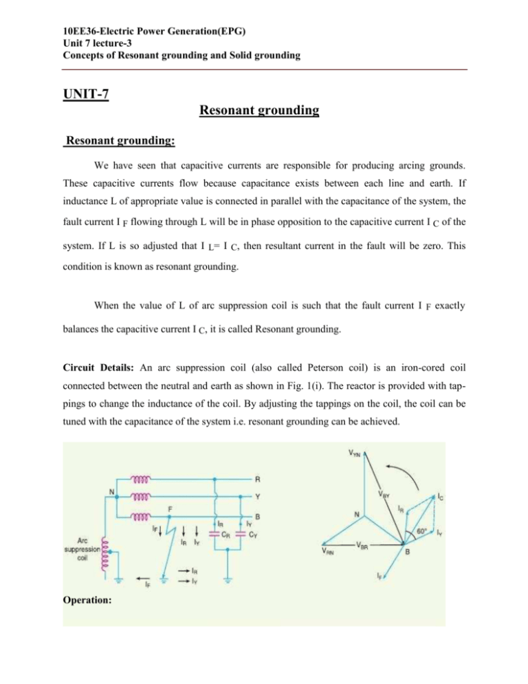
10EE36-Electric Power Generation(EPG) Unit 7 lecture-3 Concepts of Resonant grounding and Solid grounding UNIT-7 Resonant grounding Resonant grounding: We have seen that capacitive currents are responsible for producing arcing grounds. These capacitive currents flow because capacitance exists between each line and earth. If inductance L of appropriate value is connected in parallel with the capacitance of the system, the fault current I F flowing through L will be in phase opposition to the capacitive current I C of the system. If L is so adjusted that I L= I C, then resultant current in the fault will be zero. This condition is known as resonant grounding. When the value of L of arc suppression coil is such that the fault current I F exactly balances the capacitive current I C, it is called Resonant grounding. Circuit Details: An arc suppression coil (also called Peterson coil) is an iron-cored coil connected between the neutral and earth as shown in Fig. 1(i). The reactor is provided with tappings to change the inductance of the coil. By adjusting the tappings on the coil, the coil can be tuned with the capacitance of the system i.e. resonant grounding can be achieved. Operation: Fig. 1(i) shows the 3-phase system employing Peterson coil grounding. Sup-pose line to ground fault occurs in the line B at point F. The fault current I F and capacitive currents I Rand I Y will flow as shown in Fig. 1(i). Note that I F flows through the Peterson coil (or Arc suppression coil) to neutral and back through the fault. The total capacitive current I C is the phasor sum of I R and I Y as shown in phasor diagram in Fig. 1(ii). The voltage of the faulty phase is applied across the arc suppression coil. Therefore, fault current I F lags the faulty phase voltage by90°. current I F is in phase opposition to capacitive current I C [See Fig. 1(ii)]. By adjusting the tappings on the Peterson coil, the resultant current in the fault can be reduced. If inductance of the coil is so adjusted that I L= I C then resultant current in the fault will be zero Solid grounding: A solidly grounded system is one in which the neutral points have been intentionally connected to earth ground with a conductor having no intentional impedance, as shown in Figure 4. This partially reduces the problem of transient over voltages found on the ungrounded system, provided the ground fault current is in the range of 25 to 100% of the system three phase fault current. However, if the reactance of the generator or transformer is too great, the problem of transient over voltages will not be solved. While solidly grounded systems are an improvement over ungrounded systems, and speed up the location of faults, they lack the current limiting ability of resistance grounding and the extra protection this provides. Solidly grounded systems are usually limited to older low voltage applications at 600 volts or less. When the neutral point of a 3-phase system (e.g. 3- phase generator, 3-phase transformer etc.) is directly connected to earth (i.e. soil) through a wire of negligible resistance and reactance, it is called Solid grounding or effective grounding. Fig. 2 shows the solid grounding of the neural point. Since the neutral point is directly connected to earth through a wire, the neutral point is held at earth potential under all conditions. Therefore, under fault conditions, the voltage of any conductor to earth will not exceed the normal phase voltage of the system. Advantages: The solid grounding of neutral point has the following advantages: (i)The neutral is effectively held at earth potential. (ii)When there is an earth fault on any phase of the system, the phase to earth voltage of the faulty phase becomes zero. However, the phase to earth voltages of the remaining two healthy phases remain at normal phase voltage because the potential of the neutral is fixed at earth Potential. This permits to insulate the equipment for phase voltage. Therefore, there is a saving in the cost of equipment. (iii)It becomes easier to protect the system from earth faults which frequently occur on the system. When there is an earth fault on any phase of the system, a large fault current flows between the fault point and the grounded neutral. This permits the easy operation of earth-fault relay. Disadvantages: The following are the disadvantages of solid grounding (i)Since most of the faults on an overhead system are phase to earth faults, the system has to bear a large number of severe shocks. This causes the system to become unstable. (ii)The solid grounding results in heavy earth fault currents. Since the fault has to be cleared by the circuit breakers, the heavy earth fault currents may cause the burning of circuit breaker contacts. (iii)The increased earth fault current results in greater interference in the neighbouring communication lines. Applications: Solid grounding is usually employed where the circuit impedance is sufficiently high so as to keep the earth fault current within safe limits. This system of grounding is used for voltages upto 33 kV with total power capacity not exceeding 5000 kVA
