Large eddy simulation of Isothermal Swirling Flow
advertisement
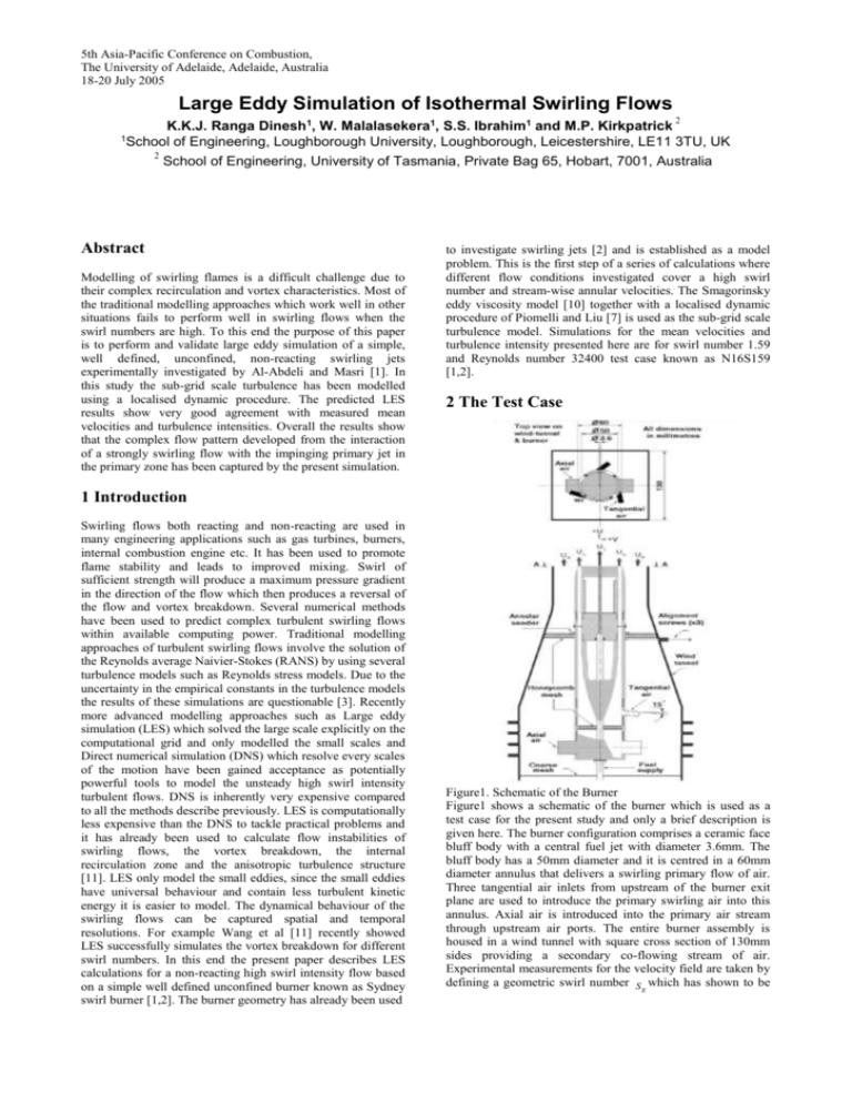
5th Asia-Pacific Conference on Combustion, The University of Adelaide, Adelaide, Australia 18-20 July 2005 Large Eddy Simulation of Isothermal Swirling Flows 2 K.K.J. Ranga Dinesh1, W. Malalasekera1, S.S. Ibrahim1 and M.P. Kirkpatrick 1School of Engineering, Loughborough University, Loughborough, Leicestershire, LE11 3TU, UK 2 School of Engineering, University of Tasmania, Private Bag 65, Hobart, 7001, Australia Abstract Modelling of swirling flames is a difficult challenge due to their complex recirculation and vortex characteristics. Most of the traditional modelling approaches which work well in other situations fails to perform well in swirling flows when the swirl numbers are high. To this end the purpose of this paper is to perform and validate large eddy simulation of a simple, well defined, unconfined, non-reacting swirling jets experimentally investigated by Al-Abdeli and Masri [1]. In this study the sub-grid scale turbulence has been modelled using a localised dynamic procedure. The predicted LES results show very good agreement with measured mean velocities and turbulence intensities. Overall the results show that the complex flow pattern developed from the interaction of a strongly swirling flow with the impinging primary jet in the primary zone has been captured by the present simulation. to investigate swirling jets [2] and is established as a model problem. This is the first step of a series of calculations where different flow conditions investigated cover a high swirl number and stream-wise annular velocities. The Smagorinsky eddy viscosity model [10] together with a localised dynamic procedure of Piomelli and Liu [7] is used as the sub-grid scale turbulence model. Simulations for the mean velocities and turbulence intensity presented here are for swirl number 1.59 and Reynolds number 32400 test case known as N16S159 [1,2]. 2 The Test Case 1 Introduction Swirling flows both reacting and non-reacting are used in many engineering applications such as gas turbines, burners, internal combustion engine etc. It has been used to promote flame stability and leads to improved mixing. Swirl of sufficient strength will produce a maximum pressure gradient in the direction of the flow which then produces a reversal of the flow and vortex breakdown. Several numerical methods have been used to predict complex turbulent swirling flows within available computing power. Traditional modelling approaches of turbulent swirling flows involve the solution of the Reynolds average Naivier-Stokes (RANS) by using several turbulence models such as Reynolds stress models. Due to the uncertainty in the empirical constants in the turbulence models the results of these simulations are questionable [3]. Recently more advanced modelling approaches such as Large eddy simulation (LES) which solved the large scale explicitly on the computational grid and only modelled the small scales and Direct numerical simulation (DNS) which resolve every scales of the motion have been gained acceptance as potentially powerful tools to model the unsteady high swirl intensity turbulent flows. DNS is inherently very expensive compared to all the methods describe previously. LES is computationally less expensive than the DNS to tackle practical problems and it has already been used to calculate flow instabilities of swirling flows, the vortex breakdown, the internal recirculation zone and the anisotropic turbulence structure [11]. LES only model the small eddies, since the small eddies have universal behaviour and contain less turbulent kinetic energy it is easier to model. The dynamical behaviour of the swirling flows can be captured spatial and temporal resolutions. For example Wang et al [11] recently showed LES successfully simulates the vortex breakdown for different swirl numbers. In this end the present paper describes LES calculations for a non-reacting high swirl intensity flow based on a simple well defined unconfined burner known as Sydney swirl burner [1,2]. The burner geometry has already been used Figure1. Schematic of the Burner Figure1 shows a schematic of the burner which is used as a test case for the present study and only a brief description is given here. The burner configuration comprises a ceramic face bluff body with a central fuel jet with diameter 3.6mm. The bluff body has a 50mm diameter and it is centred in a 60mm diameter annulus that delivers a swirling primary flow of air. Three tangential air inlets from upstream of the burner exit plane are used to introduce the primary swirling air into this annulus. Axial air is introduced into the primary air stream through upstream air ports. The entire burner assembly is housed in a wind tunnel with square cross section of 130mm sides providing a secondary co-flowing stream of air. Experimental measurements for the velocity field are taken by defining a geometric swirl number S g which has shown to be linearly proportional to the actual swirl number s defined in terms of bulk axial velocity and the outer radius of the annulus [2]. The bulk jet velocity of the fuel inlet U j , the bulk axial The Smagorinsky eddy viscosity [10] model is used to model the turbulence in sub-grid scales. The sub-grid scale stress ij (uiu j u i u j ) is modeled as and tangential velocity of the primary air stream 1 3 ij ij kk 2 sgs S ij U s and Ws are the three parameters which control the stability characteristics and physical properties of the flow. The co-flowing secondary air stream U e may influence the flow. The geometric swirl number S g is expressed here as the ratio of integrated (bulk) tangential to primary axial air velocities ( Ws U s ). The swirl number can be varied by changing the relative flow rates of tangential and axial air in the primary stream. The Reynolds number of the annulus swirling air stream is defining in terms of bulk axial velocity U s and the outer radius of the annulus rs . Flow Case N16S159 Uj (m/s) 66 Flow Isothermal Ue (m/s) 20 Us (m/s) 16.3 Sg 1.59 Ws (m/s) 25.9 Re 32400 with the eddy viscosity sgs is a function of the filter size and the strain rate S such that 2 sgs C S The localised dynamic procedure of Piomelli and Liu [7] is used to calculate the model coefficient C and length scales L ij such that C ( Lij 2C * Bij ) Aij 2 Akl Akl 2 Where A 2 S S ij B S S ij with Lij u i u j u i u j ij ij 2 * and C is the previous time step value of C . 4 Computational Details Table1. Flow conditions and control parameters 3 Numerical Modelling The governing conservation equations are filtered to remove fluctuations that cannot be resolved by the numerical method. Application of a spatial box filter to the governing equations is used to partition the solution space into resolved and sub-grid scales. The application of the spatial filter G to a function f is defined as f ( x) f ( x)G( x x' , )dx' The simulations are performed with the large eddy simulation code PUFFIN [5,6]. The equations are discretised in space by using a finite volume formulation on a non-uniform Cartesian grid. The grid has 120 120 100 cells in x, y and z directions respectively. Cells within the central recirculation region are uniform size in x, y and z directions with x y 1mm and z 1.5mm .To reduce the computational time the grid is expanded outside the central recirculation region with the grid expansion ratio 1.05. Where the integration is carried out over the entire flow domain and is the characteristic width of the filter. 3.1 Governing Equations The following set of spatially filtered time dependent equations are used as governing equations. Conservation of mass ( u j ) t x j 0 Conservation of momentum ij ui P (ui u j ) (2 S ij ) gi t x j xi x j x j Where the over-bar is the spatial filtering operator, g i is the acceleration due to gravity, P is the pressure, is the density, is the dynamic viscosity, ij is the sub-grid scale stress and S ij is the large scale strain rate tensor given by 1 u i u j S ij ( ) 2 x j xi We note that, while these simulations are of isothermal nonreacting flow, we include density explicitly as the same equations will later be used to model the non-isothermal reacting flow case. 3.2 SGS Turbulence modeling Figure2. Vertical section of the computational domain in the XZ plane The momentum and pressure correction equation are spatially discretised by using a second order central difference scheme. The time marching step is obtained by using third order hybrid Adams-Bashforth/Adams-Moulton (ABAM) scheme. A BiConjugate Gradient Stabilised (BICGStab) solver is used to solve the system of algebraic equations resulting from the discretisation. Unlike the original dynamic procedure which requires spatial averaging of the model coefficient in directions in which the turbulence can be considered homogeneous, the localised procedure of Piomelli and Liu [7] does not require spatial averaging. This is a significant advantage for complex flows such as the case presented here. The mean velocity profiles together with randomly generated turbulent fluctuations are used to define the inlet boundary conditions for the fuel and primary air annulus streams. Impermeable, free slip boundaries are used on the sides of the domain. While the top boundary is an outlet in which gradient normal to the boundary surface are set to be zero. 30 5 Results and Discussion 80 x=6.8mm 60 Mean swirl velocity (m/s) 40 40 Mean axial velocity (m/s) 0 0 40 30 10 20 30 0 0 40 30 x=20mm 10 30 20 30 40 20 x=20mm 20 30 10 20 30 40 30 40 x=30mm 15 20 10 10 0 0 20 5 10 20 30 40 0 0 15 x=40mm 15 10 20 x=70mm 10 10 5 5 0 0 10 20 30 40 0 0 10 x=100mm 8 8 6 6 4 4 00 10 0 0 x=10mm 10 20 30 40 x=125mm 2 10 20 30 40 00 10 20 30 40 40 Radial position, mm Radial position, mm Figure 5. Radial profiles for the mean swirl velocity x=30mm 20 20 10 10 0 0 20 0 10 20 30 40 0 15 10 10 5 5 0 0 10 20 30 0 0 40 20 x=100mm 15 15 10 10 5 00 10 20 x=40mm 15 20 20 30 40 x=70mm 10 20 30 40 x=125mm Figures 3, 4 and 5 show comparisons between measured and computed radial profiles for the mean axial, radial and swirling velocities at various downstream axial positions. The overall agreement between measured and computed values is excellent at almost all axial positions. According to the predicted mean axial velocity the rotating central recirculation zone is extended to about 60mm downstream of the cylindrical bluff body of the burner 5 10 20 30 40 0 10 20 30 40 30 Radial position, mm Radial position, mm Figure 3. Radial profiles for the mean axial velocity 2 0 0 -2 -2 -4 0 10 20 20 30 40 -4 0 10 0 0 -10 -10 -200 -200 20 20 30 10 20 x=20mm 10 10 x=10mm 4 2 40 30 40 x=30mm 10 20 10 10 20 30 40 x=70mm 5 0 30 10 20 30 40 x=20mm 20 10 10 00 20 10 20 30 40 x=40mm 15 15 10 10 5 00 20 30 40 20 x=100mm 15 10 10 20 30 40 x=100mm 4 -100 20 30 40 2 0 0 -2 -2 10 20 30 40 -4 0 10 20 30 20 30 40 30 40 x=30mm 10 20 x=70mm 10 20 30 40 x=125mm 10 20 30 40 00 10 20 30 40 Radial position, mm Radial position, mm Figure 6. Radial profiles for the rms axial velocity x=125mm 4 2 -4 0 10 10 5 -5 10 00 15 00 x=10mm 5 10 5 -200 00 20 0 -10 00 30 20 20 10 x=40mm 10 20 Rms axial velocity (m/s) x=6.8mm 4 30 x=6.8mm 20 00 Mean radial velocity (m/s ) 10 2 20 20 10 10 x=10mm 60 20 0 0 A comparison of experimental results [1,2] and LES computational results are presented here. The experimental measurements for the axial, radial and swirling velocities are available at different downstream horizontal planes measured from the burner exit plane. These measurements have been taken for eight different axial positions (x) varying from x=6.8mm to x=125mm. The following figures shows the comparisons between experimental (symbols) and LES calculations (slid lines) for the mean velocities and root mean square fluctuations (rms) for a test case known as N16S159 [1,2] . 30 x=6.8mm 20 40 Radial position, mm Radial position, mm Figure 4. Radial profiles for the mean radial velocity 15 x=6.8mm x=10mm 10 10 5 5 Rms radial velocity (m/s ) 00 20 10 20 30 40 00 20 x=20mm 15 15 10 10 5 00 20 20 30 40 00 20 x=40mm 15 10 10 5 20 30 40 6 Conclusions 10 20 30 40 30 40 x=70mm 5 10 20 30 40 00 20 x=100mm 15 15 10 10 5 00 20 x=30mm 5 10 15 00 10 to be a way forward to calculate important turbulent characteristics of the flow which forms the basis of combustion modelling. We intend to extend our studies to reacting cases and validate LES predictions against available experimental data. 10 20 x=125mm 5 10 20 30 40 00 10 20 30 40 Radial position, mm Radial position, mm Figure 7. Radial profiles for the rms radial velocity This paper describes the computational simulation based on LES of a non-reacting high swirl flow test case experimentally investigated by Al-Abdeli and Masri [1]. The predicted results show very good agreement for the mean and rms fluctuation of velocities. The simulation shows a strong swirling recirculation zone starting from near the bluff-body and spreading into further downstream up to 60mm from the burner exit plane. DNS is also used to investigate the basic form of the vortex breakdown for low Reynolds and swirl numbers [4],[9] and it has been observed that LES is computationally efficient and realistic than DNS to analyse the high Reynolds and swirl number flows. This study demonstrates that LES is promising method for the investigation of industrial application with complex swirling flow structures. 7 References 20 20 x=6.8mm 15 15 10 10 5 Rms swirl velocity (m/s) 00 20 20 30 40 x=20mm 00 20 15 10 10 5 20 20 30 40 x=40mm 00 20 15 10 10 5 20 20 30 40 30 40 30 40 x=30mm 10 20 x=70mm 5 10 20 30 40 x=100mm 00 20 15 15 10 10 5 00 10 5 10 15 00 [1] 5 10 15 00 x=10mm 10 20 x=125mm 5 10 20 30 40 00 10 20 30 40 Radial position, mm Radial position, mm Figure 8. Radial profiles for the rams swirl velocity Figures 6, 7 and 8 show comparisons between measured and computed radial profiles for the root mean square (rms) axial, radial and swirling velocities at various downstream axial positions. Despite the simplicity of the method used to generate instantaneous flow conditions at the inlet it gives good agreement between measured and computed values at most of the axial positions. Overall results show very good agreement with available data for other non-reacting cases as well (not presented here). The test case presented here has the highest swirl number test case with swirl number 1.59 and Reynolds number 32400 which is perceived to be the most challenging for computations. The level of agreement seen here is quite promising and LES to adopt as an accurate tool for combustion predictions in practical applications. In reacting cases where turbulence play a major role LES seems Al-Abdeli, Y.M, Masri, A.R. , Recirculation and flow field regimes of unconfined non-reacting swirling flows, Experimental and Thermal Science, 23, 2003, 655-665. [2] Al- Abdeli, Y.M, Experiments in turbulent swirling nonpremixed flames and isothermal flows, PhD Thesis, School of Aerospace, Mechanical and Mechatronic Engineering , University of Sydney, 2003. [3] Benito, A.P, The applications of second order turbulent closures to isothermal and combusting swirling flows, PhD Thesis , Department of Chemical Engineering, Imperial college of Science and Technology, 1989. [4] Kollmann, W, Ooi, A, Chang, M and Soria, J, Direct numerical simulation of vortex breakdown in swirling flows, Journal of Turbulence, 2, 2005, 1-17. [5] Kirkpatrick, M.P, Large eddy simulation code for industrial and environmental flows, PhD Thesis, School of Aerospace, Mechanical and Mechatronic Engineering , University of Sydney, 2002. [6] Kirkpatrick, M.P, Armfield, S.W, Masri, A.R and Ibrahim, S.S, Large eddy simulation of a propagating turbulent premixed flame, Flow Turbulence and Combustion, 70, 2003, 1-19. [7] Piomelli , U and Liu, J, Large eddy simulation of channel flows using a localised dynamic model, Physics of Fluids, 7, 1995, 839-848. [8] Pierce, C.D and Moin. P, Method for generating equilibrium swirling inflow conditions, AIAA Journal 36(7), 1998, 1325-1327. [9] Ruith, M.R, Chen, P, Meiburg, E and Maxworthy, T, Three Dimensional vortex breakdown in swirling jets and wakes:Direct numerical simulation, Journal of fluid mechanics, 486, 2003, 331-378. [10] Smagorinsky, J, General circulation experiments with the primitive equations, Monthly Weather Review, 91, 1963, 99-164. [11] Wang, P, Bai, X.S, Wessmand, M and Klingmann, J, Large eddy simulation and experimental studies of confined turbulent swirling flows, Physics of fluids, 16, 2004, 3306-3324.
