notes
advertisement
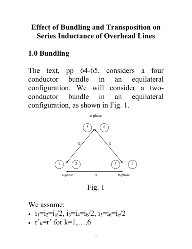
Effect of Bundling and Transposition on Series Inductance of Overhead Lines 1.0 Bundling The text, pp 64-65, considers a four conductor bundle in an equilateral configuration. We will consider a twoconductor bundle in an equilateral configuration, as shown in Fig. 1. c-phase 5 6 D 1 D 2 a-phase 3 D 4 b-phase Fig. 1 We assume: i1=i2=ia/2, i3=i4=ib/2, i5=i6=ic/2 r’k=r’ for k=1,…,6 1 Recall our eq. (31) which is the same as eq. 3.22 in the text: k 0 2 1 1 1 1 i2 ln ... ik ln ... in ln i1 ln (31) d k1 dk 2 rk d kn Apply this to the configuration of Fig 1, for conductor #1. 0 2 ia ib ib ic ib 1 ia 1 1 1 1 1 ln ln ln ln ln ln 2 r 2 d 12 2 d 13 2 d 14 2 d 15 2 d 16 i i i 1 1 1 0 a ln b ln c ln 2 2 r d 12 2 d 13 d 14 2 d 15 d 16 1 Bring ½ into the logarithm. 1 0 2 1 1 1 i ln i ln i ln a b c ( r d 12 )1 / 2 (d 13 d 14 )1 / 2 (d 15 d 16 )1 / 2 Define: Geometric Mean Radius (GMR) of bundle Rb=(r’d12)1/2 Geometric Mean Distance (GMD) between phase positions o From phase a to phase b D1b=(d13d14)1/2 ≈(D2)1/2=D o From phase a to phase c D1c=(d15d16)1/2 ≈(D2)1/2=D 2 Substituting D into the last expression for λ1 1 0 2 1 1 1 i b ln i c ln i a ln Rb D D (1) Factor out the ln(1/D): 1 0 2 1 1 ln i b i c i a ln Rb D (2) Assuming balanced conditions, so that ib+ic=-ia, we have 1 0 2 1 1 0 ia D i ln i ln ln a a Rb D 2 Rb Use l=λ/i to get inductance of conductor 1: l1 0 ia i D D ln 2 0 a ln 2 ( ia / 2) Rb 2 Rb We can repeat the process for conductor 2, which is the other conductor in the phase a bundle. We will obtain: l2 2 0 ia D ln 2 Rb Since we have two equal conductors in parallel, the phase a inductance is just: la l1 0 i a D ln 2 2 Rb Since we have an equilateral configuration of the phases, 3 0 D lb lc la ln 2 Rb (3) Recall the solution to example 3.2 in the text where we had equilateral configuration but no bundling, i.e., only 1 conductor per phase. In this case, 0 D lb lc la ln 2 r (4) Note that the only difference between the inductance expression for bundled (3) and non-bundled (4) equilateral configurations is the use of Rb for bundled case vs. the use of r’ for non-bundled case, where Rb=(r’d12)1/2. How does Rb related to r’? To answer this question, note that it will always be the case that the distance of separation between conductors in a bundle 4 will exceed the radius of a conductor, i.e., d12>r’ (Even Fig. 1, which is not drawn to scale, would suggest this). The implication of this fact on Rb=(r’d12)1/2 is that Rb>r’. Therefore, D/Rb<D/r’. Therefore ln (D/Rb)<ln (D/r’). Therefore the inductance of a bundled conductor configuration is less than the inductance of a non-bundled conductor configuration, given the same D. Therefore the reactance of a bundled conductor configuration is less than the reactance of a non-bundled conductor configuration, given the same D. In the text’s treatment of the case of 4 conductors per bundle, they get the same eq. (3), but Rb=(r’d12d13d14)1/4. 5 In general for bundled conductors with b conductors per bundle, Rb=(r’d12…d1b)1/b. Question: As we increase b, what does geometry tend to become? b=2 b=5 b=3 b=6 b=4 b=8 Fig. 2 We observe that as b gets large, the bundle begins to take on the configuration of a circle, with all current flowing at the 6 circumference. A hollow conductor!!!! So the denominator Rb tends from r’ (for the case of b=1) to the radius of the circle comprised by the bundle as b gets large. Exercise 1: It asks you to look at the case of b=31 when conductors are located around the circumference of a circle of radius=1 ft, with conductor radius=0.1 ftr’=0.078 ft. The circle would have a circumference of 2π. Therefore, the spacing between 31 conductors would be (along the arc of the circle) 2π/31≈0.2. 7 1 ft Fig. 3 The problem is asking you to graphically measure the distance from the dark conductor to every other conductor. Then compute Rb=(r’d12d13d14…d131)1/31. You should get ~1.0 ft. Compare to r’=0.078 ft for single conductor without bundling. The basic concept to be absorbed here is that increasing Rb of the bundle lowers the inductance. The reason for this is that, as b gets large, there is less and less flux interior 8 to the “circle” and therefore less flux linking the conductors. When b is very large, there is no flux interior to the circle, which is the case of the hollow conductor. Reference [1] indicates the following usages of bundling: 345 kV: 1 or 2 conductors per phase 500 kV: 1, 2, 3, or 4 conductors per phase 765 kV: 3, 4, 6, or 8 conductors per phase 2.0 Stranding The procedure used above to obtain Rb may also be applied to the case of a stranded conductor, where a single conductor consists of several individual strands. See problem 3.7 on how to compute RS, the GMR of a stranded conductor in a threephase equilateral geometry. Problem 3.8 gets a numerical answer for this case. Can work these problems in-class (see notes). 9 The bottom of page 70 in your text discusses the difference in computing GMR for a conductor considering stranding (as done in Problems 3.7 and 3.8) vs. not considering stranding (simply using r’=0.778r, where r is the radius of the conductor), concluding “even if we ignore the stranding, our results are quite accurate.” Comparison of the answers to Problems 3.9 and 3.10, and of the answers to Problems 3.12 and 3.13, confirm this conclusion. 3.0 Transposition From structural point of view, it is more economic to arrange the phases of a transmission line in a vertical or horizontal configuration, as shown in Fig. 4. 10 Fig. 4 These and other arrangements are not symmetric like the equilateral configuration is. This means that la=lb=lc is not valid. If you have such an arrangement, and you apply balanced voltages to the sending end of this transmission line, and connect it to a balanced load, you will not see a balanced current flow. This has effects which are not desirable (e.g., neutral current is not zero, also generation of negative and zero sequence currents causes increased heating in loads). 11 To address this, line designers use transposition where line positions are interchanged. Position interchange is typically done at substations. We want to determine the influence of transposition. Let’s make the following assumptions: 1.The line is “completely” transposed. This means that each phase occupies each position for the same fraction of total length. This assumption allows us to compute the flux linkages for a phase by averaging flux linkages over all three positions. That is: a 1 ( 1) a (a2) (a3) 3 (3) where the overbar indicates “average” and (k ) the nomenclature a , k=1,2,3, is the flux linkages computed for phase a when located at position k. 2.Currents are balanced, i.e., ia+ib+ic=0. 12 3.The line is bundled. Note that assumption #3 is a departure from the text. The text (page 68) first does the non-bundled case and then uses that result to get the bundled case. In contrast, we will do both cases at the same time. Recall eq. (1), repeated here for convenience, which is the flux linkages for a bundled conductor with dab=dbc=dca=D. 1 0 2 1 1 1 i b ln i c ln i a ln Rb D D (1) This equation also applies to our case, but we need to change the denominators of the second two terms. (ak ) 0 2 1 1 1 i ln i ln i ln a b c (k ) (k ) , Rb d ab d ac k=1,2,3 (5) where Rb is the GMR of the bundle given by: Rb r d12 , 1/ 2 1/ 3 r d12d13 , for 2 conductor bundle for 3 conductor bundle 1/ 3 r d12d13d14 , for 4 conductor bundle 13 So substitution of eq. (5) for k=1,2,3 into eq. (3) to get the average flux linkages, yields: 1 (1) a (a2 ) (a3 ) 3 1 0 1 1 1 i ln i ln i ln a b c (1) (1) 3 2 Rb d ab d ac a ia ln 1 1 1 ib ln ( 2 ) ic ln ( 2 ) Rb d ab d ac (6) 1 1 1 ia ln ib ln ( 3 ) ic ln ( 3 ) Rb d ab d ac Adding terms that are multiplied by the same current, we get: a 1 3 i ln a Rb 1 1 1 ib ln (1) ln ( 2 ) ln ( 3 ) d ab d ab d ab 1 0 3 2 1 1 1 ic ln (1) ln ( 2 ) ln ( 3 ) d ac d ac d ac (7) Now combine logarithms in the second 2 terms: 14 1 0 1 1 1 a ib ln (1) ( 2 ) ( 3 ) ic ln (1) ( 2 ) ( 3 ) 3ia ln 3 2 Rb d ab d ab d ab d ac d ac d ac (8) Now bring the 1/3 into the logarithms: a 0 2 1 1 i ln i ln a b (1) ( 2 ) ( 3 ) R d ab d ab d ab b 1/ 3 ic ln d 1 (1) ac ( 2) ( 3) d ac d ac (9) (1) ( 2 ) ( 3 ) (1) ( 2 ) ( 3 ) d d d d ac d ac d ac Note that ab ab ab because this is just the product of the distances between the positions. So we define: d (1) ( 2 ) ( 3 ) 1 / 3 ab ab ab d (1) ( 2 ) ( 3 ) 1 / 3 ac ac ac Dm d d d d (10) where Dm is the GMD between positions. Substitution of eq. (10) into eq. (9) yields: 0 1 1 1 a ib ln ic ln ia ln 2 Rb Dm Dm But ia=-(ib+ic), so that eq. (11) becomes: 15 (11) 1/ 3 a 0 2 0 1 1 1 1 i ln ln i i i ln i ln a a b c a R D 2 R D b m b m (12) Factoring out ia and combining logarithms, we get: a 0 ia Dm ln 2 Rb (13) The inductance is then obtained by dividing by the current ia to get: la a ia 0 Dm ln 2 Rb (14) where Dm is the GMD between phase positions Rb is the GMR of the bundle Note that if the phase configuration is equilateral, then Dm=D if the conductor is not bundled, then Rb=r’ We will skip section 3.6. You should take EE 455 to learn about getting inductance for the unbalanced line. 16 [1] “Transmission Line Reference Book: 345 kV and Above,” EPRI, second edition, 1982. 17
