Mathematical modeling of a hydraulic system equipped with a pipe
advertisement

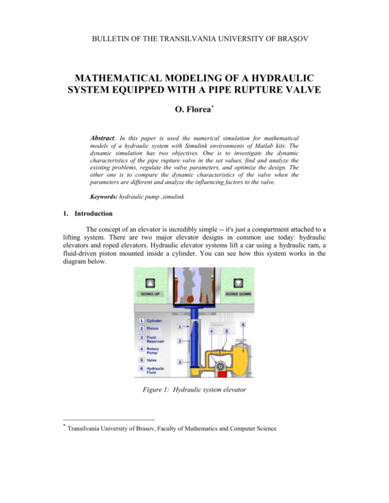
BULLETIN OF THE TRANSILVANIA UNIVERSITY OF BRAŞOV MATHEMATICAL MODELING OF A HYDRAULIC SYSTEM EQUIPPED WITH A PIPE RUPTURE VALVE O. Florea* Abstract. In this paper is used the numerical simulation for mathematical models of a hydraulic system with Simulink environments of Matlab kits. The dynamic simulation has two objectives. One is to investigate the dynamic characteristics of the pipe rupture valve in the set values, find and analyze the existing problems, regulate the valve parameters, and optimize the design. The other one is to compare the dynamic characteristics of the valve when the parameters are different and analyze the influencing factors to the valve. Keywords: hydraulic pump ,simulink 1. Introduction The concept of an elevator is incredibly simple -- it's just a compartment attached to a lifting system. There are two major elevator designs in common use today: hydraulic elevators and roped elevators. Hydraulic elevator systems lift a car using a hydraulic ram, a fluid-driven piston mounted inside a cylinder. You can see how this system works in the diagram below. Figure 1: Hydraulic system elevator * Transilvania University of Brasov, Faculty of Mathematics and Computer Science 154 Mathematical modeling of a hydraulic system equipped with a pipe rupture valve The cylinder is connected to a fluid-pumping system (typically, hydraulic systems like this use oil, but other incompressible fluids would also work). The hydraulic system has three parts: A tank (the fluid reservoir) A pump, powered by an electric motor A valve between the cylinder and the reservoir The pump forces fluid from the tank into a pipe leading to the cylinder. When the valve is opened, the pressurized fluid will take the path of least resistance and return to the fluid reservoir. But when the valve is closed, the pressurized fluid has nowhere to go except into the cylinder. As the fluid collects in the cylinder, it pushes the piston up, lifting the elevator car. In the hydraulic elevator is used the pipe rupture valve for automatic change of the flow rate. This is installed near the entrance in the hydraulic cylinder. In ordinary conditions this has no effect, but in case of accidents when the elevator fall quickly, the flow rate through the pipe rupture valve grow up. When the pressure value of failure excel the initial value, the valve shut off quickly and the lift stop from the falling, guarantee the safety of passengers. After the damage is eliminated, the force through the pump and the spring force act together for open valve and make that the system works normally. 2. Analysis and simulation of system The rupture valve model is mainly applied in the elevator hydraulic system; so that the dynamical characteristics of the hydraulic system must be take in consideration, and the factors which effects are insignificant will be neglect during the simulation model. The simulation principle of the rupture valve is presented in the figure 2; this model presents the application of the rupture valve in the elevator hydraulic system. Figure 2: Diagram of rupture valve of hydraulic elevator Bulletin of the Transilvania University of Braşov • Vol.13(48) - 2006 155 2.1 Mathematical Model The equation of pressure is: pt p p K f (qVc qVs ) 2 (1) Here: p t is the pressure between the out port of the pump and the admission port of the rupture valve, p p is the pressure in the out port of the pump, K f is the friction coefficient, qVc is the flow rate through the valve, qVs is the flow rate through the chamber. The chamber by the back rupture valve is closed so the equation of continuity is: Vs dp s dx As qVs C s ( p s pt ) E dt dt (2) Here: Vs is the volume from the back of chamber, E is the spring bulk modulus of the dx is the motion of the dt valve, C s is the trickling coefficient through the back cavity and the valve’s body, p s is the hydraulic oil in the back chamber, As is the section of the valve, pressure in the back chamber. The pressure difference through the rupture valve is making by the flow through the pipe and the orifice. The differential equation of the flow rate and of the pressure is: 2 p c pt K d qVc 2 2 qVc 1 C A22 2 2 (3) Here: pc is the pressure in valve, K d is the flow rate coefficient, is the hydraulic density of oil, C2 is the debit coefficient through the valve’s port, A2 is the valve’s section. The equilibrium equation of the valve is: m d 2x Fp F1 F2 F f Fs FRv dt 2 (4) Where, F p ( p c p s ) As , F1 K 1 ( x0 x)( p c pt ) dx p c pt , F f K f ( p s pt ) (5) F2 K 2 dt dx Fs ( F0 K s x), FRv Bs dt Here, m is the spool mass, Fp is the force produced by the pressure differential between both ends of the valve spool; F1 is the stabilization hydraulic force, F2 is the dynamic hydraulic force, F f is the friction force, FRv is the resistance viscous force, x0 initial displacement, 156 Mathematical modeling of a hydraulic system equipped with a pipe rupture valve x is the spool displacement, F0 is elastic force, K s is the elastic coefficient, Bs is the resistance coefficient of the spool’s valve. Between the hydraulic cylinder and the rupture valve is a closed chamber. The equation of continuity of the flow rate is: Vc dpc dy Ac qVc Cv ( pc pt ) Ct pc Ec dt dt (6) Here, Vc is the volume of the closed chamber, Ec is the spring modulus of the hydraulic oil, dy is the speed of the piston in the hydraulic cylinder, C v is the flow coefficient between dt the spool element of the valve and the body of the valve and C t is the flow coefficient through the outer of the hydraulic cylinder. In this model the positive direction is in the sense of the lift descend. The equation of the equilibrium in the cylinders is: d2y dy mc g pc Ac Bc Fc 2 dt dt Here, Bc is the viscous damping coefficient and Fc is the friction force. mc (7) Equations (1) – (7) are the mathematical models of the pipe rupture valve in the hydraulic elevator system. The analogical networks of numerical simulation attached to these equations are according with the null initial conditions and can describe transitional phenomena of general amplitude. The hydraulic lift system is presented in the network form figure 3, which contains six parts corresponding to the six equations describing the mathematic model. Figure 3: Simulation of hydraulic elevator system Bulletin of the Transilvania University of Braşov • Vol.13(48) - 2006 157 The movement of the hydraulic elevator is presented in figure 4 Figure 4: The evolution of the hydraulic elevator movement. Refereneces 1. Vasiliu N., Vasiliu D., :Actionari hidraulice si prneumatice, vol 1,Ed. Tehnica, 2005 2. Wesseling, P.: Principles of Computational Fluid Dynamics, Ed. Springer, 2001 3. Florea O., : Modelul matematic al unor probleme de dinamica a sistemelor hidraulice de urmărire, International Conference Nav-Mar-Edu, ISBN: 973- 8303-54-0 4. http://home.howstuffworks.com/ Modelul matematic al unui sistem hidraulic echipat cu o conducta cu valva perforata Rezumat. In lucrare este utilizata simularea numerica pentru modele matematice ale sistemelor hidraulice folosind mediul Simulink din Matlab. Simularea dinamica are doua obiective: unul este de a investiga caracteristicile dinamice ale conductei cu valva perforata, gasirea si analizarea problemelor existente, reglarea parametrilor valvei si optimizarea designului, alta este de a compara caracteristicile dinemice ale valvei cand parametrii sunt diferiti si analizarea influentei factorilor asupra valvei. Keywords: pompa hidraulica, simulink


