5th International DAAAM Baltic Conference
"INDUSTRIAL ENGINEERING – ADDING INNOVATION CAPACITY OF LABOUR
FORCE AND ENTREPRENEURS"
20–22 April 2006, Tallinn, Estonia
SYNTHESIS OF VIBRO-CUTTING SYSTEMS WITH TIME AND
ADAPTIVE CONTROL
Akinfiev, T., Armada, M. & Viba, J.
Abstract: Synthesis and production
of real vibro-technical systems must take
into account all kinds of parameters
variations: – change of machine
mechanical parameters; – change of
processing media parameters; – change of
machine control system parameters. For
this reason systems with stable control
may be used. In this paper all kinds of
parameters changes were investigated for
synthesis vibro-impact cutting systems. The
main
problem
of
synthesis
new
technological systems is to provide they
motion stability.
Key
words:
impact,
technological
processing, motion stability, adaptive
control, synthesis.
parameters is investigated for adaptive
control of spring stiffness or excitation
forces.
2. SIMPLE MODEL
CUTTING SYSTEM
OF VIBRO-
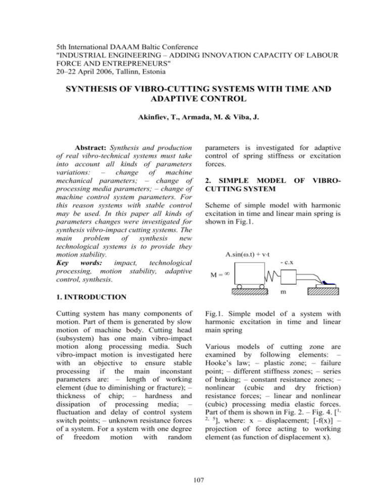
Scheme of simple model with harmonic
excitation in time and linear main spring is
shown in Fig.1.
A.sin(.t) + vt
- c.x
M=
m
1. INTRODUCTION
Cutting system has many components of
motion. Part of them is generated by slow
motion of machine body. Cutting head
(subsystem) has one main vibro-impact
motion along processing media. Such
vibro-impact motion is investigated here
with an objective to ensure stable
processing if the main inconstant
parameters are: – length of working
element (due to diminishing or fracture); –
thickness of chip; – hardness and
dissipation of processing media; –
fluctuation and delay of control system
switch points; – unknown resistance forces
of a system. For a system with one degree
of freedom motion with random
Fig.1. Simple model of a system with
harmonic excitation in time and linear
main spring
Various models of cutting zone are
examined by following elements: –
Hooke’s law; – plastic zone; – failure
point; – different stiffness zones; – series
of braking; – constant resistance zones; –
nonlinear (cubic and dry friction)
resistance forces; – linear and nonlinear
(cubic) processing media elastic forces.
Part of them is shown in Fig. 2. – Fig. 4. [1,
2, 5
], where: x – displacement; [-f(x)] –
projection of force acting to working
element (as function of displacement x).
107
0.5
- f x( )
vn
x
Fig. 2. Model of a cutting zone f(x) with
full main spring (Hooke’s law) and
triangular damping loop or mechanical
hysteresis [5].
0
0.5
0.03
0.02
0.01
0
0.01
xn
- f(x)
Fig. 5. Motion in phase plane (v – velocity;
x – displacement) with zero gaps.
Transient process is very short (about 3
cycles)
0.5
x
Fig. 3. Model of cutting zone with one –
side main spring and triangular mechanical
hysteresis
vn
0
f (x)
0.5
0
1
2
3
tn
Fig. 6. Velocity v in time t domain with
zero gaps
x
Fig.4. Model of cutting zone with full main
spring and quadrangle mechanical
hysteresis
3.
SYSTEM
EXCITATION
WITH
MIXED
Investigation of a system includes special
solutions with excitation due to parametric
stiffness variation, and force excitation for
one degree of freedom system together
with additional displacement of cleaning
head, additional deformations of working
element and breaking adherence (Fig. 7.).
The simple equation of motion is (1) [1, 2]:
The fluctuation in time of a control action
was investigated in a case when system has
zero gaps (Fig. 5, Fig. 6.). Investigations
show that for real systems it is
recommended to choose positive initial
gap.
108
C3
2
[1 A sin( p t )]} x b13 x
mx {C1 C 2
C 4 x b4 x 3
F 0 sign ( x )
4
[1 sign ( x)] [1 sign ( x )]
P0 sin( t ),
1
1
0.726723
0.5
(1)
v
n
0
0.415695
where m - mass; x - displacement; x velocity; x - acceleration; C1, C 3, C 4,
stiffnesses of springs; C2 constant of
additional stiffness variation; A, p, b13,
F0, b4, P0 – constants. Examples of
modeling are shown in Fig. 8. – Fig. 11.
0.5
0.06
0.04
0.047421
0.02
0
0.02
x
3
n 3.944521 10
Fig. 9. Motion in phase plane in a case of
second resonance
1.084859
Robot Cleaning head
co+c1.sin(w1t)
v
n
0.5
Psin(wt)
0
0.452465 -0.5
Fig. 7. Scheme of system with mixed
excitation
0
0
1
2
t
3
n
Fig. 10. Velocity in time domain in main
resonance
0.63577
1
0.5
0.5
v
n
v
0
n
0
0.5
0.367174 0.5
0.04
0.04
0.02
0
0
x
n
0.02
3
3.437228 10
0
Fig. 8. Motion in phase plane in a case of
third resonance.
1
2
t
n
3
2.1
Fig. 11. Velocity in time domain in 0.25
resonances
109
parameters the equation of motion is the
same with difference that some parameters
are changing in time randomly. For small
exchanges the motion is stable, too (Fig.
15, Fig. 16).
4. SYSTEM WITH ADAPTIVE
CONTROL OF STIFFNESS
Scheme of system is shown in Fig. 12.
C1+C2
P0
C3
x
vx
C1
C1+C2+C3
x=0
F
C1+C3
x
O
C1+C3
Fig.12. Scheme of system with adaptive
control of stiffness by constant C2 (see
equation (2) and Fig. 13.)
C1+C2+C3
Equation of motion is following (2):
Fig. 13. Scheme of motion and
control ( x, x ) in phase plane (see (3))
mx {C1 C 3 ( x, x )) x b13 x
F 0 sign ( x )
(C 4 x b4 x 3 ) (a rnd (b))
4
[1 sign ( x )] [1 sign ( x )]
P0,
(2)
0.2
0.1
vn
where m - mass; x - displacement; x x
velocity;
acceleration;
C1,C 3 stiffness of springs; P0 constant force given by the springs initial
tensions or cleaning head weight ; - gap
when x = 0; ( x, x ) - control action; b13,
F0, C4, a, b – constants.
For adaptive control (excitation) as
change of common spring system stiffness
( x , x ) was used as function (3) (see Fig.
13.):
0
0.1
0.2
0.02
0.01
0
0.01
0.02
xn
Fig. 14. Modeling motion in phase
plane without random parameters.
Trajectories in the phase plane do not cross
and transient process is very short
0.2
C2
x x
(1
),
(3)
2
x x
where C2 - constant.
Example of motion is shown in Fig. 14. –
Fig. 16.
Motion character analysis allows conclude
that trajectories in the phase plane do not
cross and transient process is very short.
For modeling systems with random
0.1
( x , x )
vn
0
0.1
0.2
0.02
0.01
0
0.01
0.02
xn
Fig. 15. Motion in phase plane with
random parameters of cutting zone.
110
Trajectories in the phase plane do not cross
and transient process is very short
Comments about some investigation of
system are given under Fig. 18. – Fig. 21.
In the first part of motion a period exists
when vibro-impact motion increases.
After removal of the stick the second
period of vibration stop exists.
The periodic trajectory is not so irregular.
0.2
0.1
vn
0.5
0
x
n
0
0.1
0.5
0.2
1
0
5
0
10
5
t
tn
Fig. 16. Velocity in time domain
with random parameters of cutting zone
Fig. 18. Displacement of main mass in
time domain
5. SYSTEM WITH ADAPTIVE
CONTROL FOR NON-PERIODICAL
CYCLE
3.005351
3
v
n
Scheme of removal of defected adhered
blocks from main reinforced concrete
production line is shown in Fig. 17 [3, 4].
After technological cutting process a part
of the block sticks to steel plate. Attempt
to remove block by simple winches may
damage a block in vertical direction near
holes.
In this report adhered blocks problem is
solved by new vibro-impact system with
variable structure. System includes:adhered block 1; - main mass 2; - spring
with damper 3; - moving foundation 4; excitation system by harmonic vibration
force (with variable amplitude and it brake
off); - supply system.
2
4
10
n
1
1
3
2.659718
5
0
0
2
4
6
8
t
n
10
10
Fig. 19. Velocity of main mass in time
domain.
3.005351
5
v
n
0
2.659718
5
1
0.5
0.536376
0
x
n
0.5
1
0.570817
Fig. 20. Motion of main mass in phase
plane
1
3
Fig. 17. System with variable structure. 1 adhered block; 2 - main mass; 3 - spring
with damper; 4 - moving foundation with excitation system
111
148.19584
5
P
n
v
140.34304
7
5. Hibbeler, R.C. Mechanics of Materials.
PEARSON, Prentice-Hall, Inc. Singapore
629733. 2004.
20
0
0
8. CORRESPONDING AUTHOR
20
0
0
0
5
t
n
Akinfiev Teodor, professor, Dr.habil.sc.ing.
IAI CSIC, Spain,
IAI Carretera de Campo Real km 0.200 ::
Arganda del Rey :: 28500 MADRID ::
Apartado 56 :: ESPAÑA :: Tlf. (34) 91 871 19
00 :: Fax: (34) 91 871 70 50, E-mail:
teodor@iai.csic.es
1
01
0
Fig. 21. Harmonic vibration force (with
variable amplitude and brake)
6. CONCLUSION
Various new models of cutting zone
(mechanical hysteresis) are examined by
following elements: Hooke’s law, plastic
zone, failure point; - different stiffness
zones; - constant resistance zones; nonlinear (cubic and dry friction)
resistance forces; - linear and nonlinear
(cubic) processing media elastic forces and
variable system structure.
From analysis of motion character follows
that for adaptive systems trajectories in the
phase plane do not cross, and transient
process is very short. For modeling
systems with random parameters the
equation of motion is the same with
difference that some parameters are changing in time or randomly. Mechanical
problems of some systems with variable
structure are discussed.
7. REFERENCES
1. Lavendelis, E. Synthesis of optimal
vibro machines. Zinatne, Riga, 1970. (in
Russian).
2. Viba, J. Optimization and synthesis of
vibro impact systems. Zinatne, Riga, 1988.
(in Russian).
3. From Wikipedia, the free encyclopedia.
http://en.wikipedia.org/wiki/Reinforced_co
ncrete.
4. www.tmb-elements.lv.
112


