Air-cooled Chiller Functional Test
advertisement
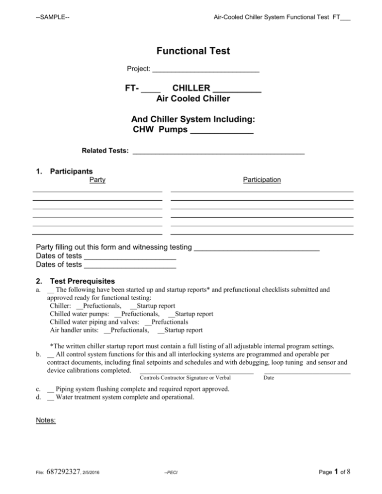
--SAMPLE-- Air-Cooled Chiller System Functional Test FT___ Functional Test Project: ____________________________ FT- ____ CHILLER __________ Air Cooled Chiller And Chiller System Including: CHW Pumps _____________ Related Tests: _____________________________________________ 1. Participants Party Participation Party filling out this form and witnessing testing ______________________________ Dates of tests ______________________ Dates of tests ______________________ 2. Test Prerequisites a. __ The following have been started up and startup reports* and prefunctional checklists submitted and approved ready for functional testing: Chiller: __Prefuctionals, __Startup report Chilled water pumps: __Prefuctionals, __Startup report Chilled water piping and valves: __Prefuctionals Air handler units: __Prefuctionals, __Startup report *The written chiller startup report must contain a full listing of all adjustable internal program settings. b. __ All control system functions for this and all interlocking systems are programmed and operable per contract documents, including final setpoints and schedules and with debugging, loop tuning and sensor and device calibrations completed. _________________________________ _________________________ Controls Contractor Signature or Verbal Date c. __ Piping system flushing complete and required report approved. d. __ Water treatment system complete and operational. Notes: File: 687292327, 2/5/2016 --PECI Page 1 of 8 --SAMPLE-- e. f. g. h. i. j. k. l. m. n. o. p. q. r. Air-Cooled Chiller System Functional Test FT___ __ Vibration control report approved (if required). __ Test and balance (TAB) complete and approved for the hydronic system. __ All A/E punchlist items to date for this equipment corrected. __ These functional test procedures reviewed and approved by installing contractor. __ Safeties and operating ranges reviewed. __ Test requirements and sequences of operation attached. __ Schedules and setpoints attached. __ False loading equipment, system and procedures ready (cross-over piping, preheat or reheat coils, control loops, over-ride on OSA dampers, etc.) __ Sufficient clearance around equipment for servicing. __ Sump or crankcase heaters have been on long enough to allow immediate starting of chillers. __ Have all energy savings control strategies, setpoints and schedules been incorporated that this chiller and control system are capable of? If not, list recommendations below. __Misc. tools needed: __two-way radios (general c.), __original calibration temperature probe (controls c.), pressure gages for evaporator dP (mechanical c.), temperature probe with 6 ft wire or data logger (commissioner), amp meter for pump amps (commissioner). __ Control Program Review. Review the software control program(s) for this equipment. Parameters, setpoints and logic sequences appear to follow the specified written sequences. __ Record made of All Values for Current Setpoints (SPt), Control Parameters, Limits, Delays, Lockouts, Schedules, Etc. Changed to Accommodate Testing: Parameter Pre-Test Values Chiller OSAT lockout Lead CHW pump ID: Lag 1 ID: 55F Returned to Pre-Test Values Parameter Pre-Test Values Returned to Pre-Test Values CWRT Setpoint Safety Overrides or Jumpers Delays/Timers 3. Sensor Calibration Checks. The sensors listed below checked for calibration and adequate location. This is a spot check on a sample of the calibrations done during prefunctional checklisting.* “In calibration” means making a reading with a calibrated test instrument within 6 inches of the site sensor. Verify that the sensor reading (via the permanent thermostat, gage or building automation system (BAS)) compared to the test instrument-measured value is within the tolerances specified in the prefunctional checklist requirements. If not, install offset in BAS, calibrate or replace sensor. Use the same test instruments as used for the original calibration, if possible. Notes: File: 687292327, 2/5/2016 --PECI Page 2 of 8 --SAMPLE-- Sensor & Location Air-Cooled Chiller System Functional Test FT___ Location OK1 1st Gage or BAS Value Final Gage Instr. or Meas’d BAS Value Value Pass Y/N? Chiller Panel Value CHWST Sensor & Location Location OK1 1st Gage Instr. or BAS Meas’d Value Value Final Gage or BAS Value Chiller Panel Value Pass Y/N? OSAT CHWRT Pump current (CWP1-CUR) 1 Sensor location is appropriate and away from causes of erratic operation. *For every sensor originally found out of calibration, check one additional sensor not listed. 4. Device Calibration Checks. The actuators or devices listed below checked for calibration. This is a spot check on a sample of the calibrations done during prefunctional checklisting and startup.** “In calibration” means observing a readout in the BAS and going to the actuator or controlled device and verifying that the BAS reading is correct. For items out of calibration or adjustment, fix now if easy, via an offset in the BAS, or a mechanical fix. Device or Actuator & Location 1st BAS Readin g Site Observation Final BAS Reading Pass Y/N Device or Actuator & Location 1st BAS Reading Site Observation Final BAS Reading Pass Y/N **For every actuator or device originally found out of calibration, check one additional one not listed. 5. Verification of Misc. Prefunctional Checks. Misc. site checks of the prefunctional checklist and startup reports completed successfully. Pass? Y / N _______ 1. Verify that in the chiller control panel, Menu 3, that input 30 is enabling a remote chilled water setpoint. Y/N _________ 2. ___All hydronic isolation valves fully open. 3. ___Hydronic balancing valves adjusted per the balance report and permanently marked. 4. ___Pull 3 strainers in strategic locations where debri collection is likely, to verify flush (list): ___All OK? 6. Notes on Methods Used to False Load Chiller (for reference, see Note 6 at end of test) ___________________________________________________________________________________________ ___________________________________________________________________________________________ ___________________________________________________________________________________________ ___________________________________________________________________________________________ 7. General Conditions of Test Notes: File: 687292327, 2/5/2016 --PECI Page 3 of 8 --SAMPLE-- Air-Cooled Chiller System Functional Test FT___ The chiller will be tested with the building in as normal mode as possible. Temperatures are expected to be in the 70’s creating sufficient load for most of the tests. False loading, lowering space setpoints and/or turning on the preheat will be employed if necessary. 8. Testing Procedures and Record Proced. No. 1. Sequ Test Procedure3 (including special conditions) ence. ID No.1 2; 3 Startup Sequence (This is not the initial startup by factory reps). a. With chiller system off, with schedule allowing chillers ON and OSAT >56F, overwrite the OSAT to be 50F. b. Return the OSAT to normal (assuming > 56F), turn chillers and pumps to auto. Turn ON only one AHU and command the cooling coil valve (CCV) to 18% open. A call for the chillers will be made when any AHU fan is ON and its CCV is => 15% open for ____minutes and OSAT is > 55F. Min. Chiller Flow. While only 1 CCV is < 20% open and the other CCV is closed: 2. 3. 2 4. 1; 6 Minimum On-Time With chiller on and running for less than 10 minutes [_________], command all cooling coil valves closed. Return CCVs to normal after procedure. Lead Pump Start Failure. Turn chiller OFF. Turn lead pump (CWP ___) to OFF; turn lag pump [CWP ____) and chiller to auto. Initiate a call for cooling per procedure 1. Expected and Actual Response4 [Write ACTUAL response in brackets or circle] Pass Y/N Note # a. Observe that the CHW pump does not come ON. b. Observe the lead CHW pump coming ON after ____ min. [_______]. Observe in the BAS that the proof of flow has been made (or see it at the chiller panel). Once there is proof of flow, observe that the chiller starts. Observe that the initial CHWST StPt is 49F [_________] in chiller panel. Record pump amps [_____] and dP across pump [_____________] and dP across CHW evaporator [___________]. Make sure amps aren’t over the RLA (________) of the pump. Plot the operating point of the pump on the pump curve and chiller O&M evap. Dp/gpm chart to estimate gpm: [curve___________ gpm, chart_____________gpm]. Make sure the gpm is greater than the minimum req’d chiller flow of 408 gpm. Observe that the chiller and pump does NOT stop until the 10 min. min ON-time is expired. Observe that after a call for the chiller is made to the lead pump for 45 seconds[ __________] an alarm is generated in the BAS [________]; and that the lag pump starts and chiller starts. Notes: File: 687292327, 2/5/2016 --PECI Page 4 of 8 --SAMPLE-- Proced. No. 5. Air-Cooled Chiller System Functional Test FT___ Sequ Test Procedure3 (including special conditions) ence. ID No.1 3, 6, Lead-1 Pump Failure. ++ With chiller having been running in auto for less than 10 minutes, and all pumps in auto, turn the operating pump (CWP_____) to OFF. 6. 1; 6 7. ++ 8. ++, 6 9. 3 10. 3 Expected and Actual Response4 [Write ACTUAL response in brackets or circle] Pass Y/N Note # Observe that the chiller stops [____________] and 2 BAS alarms are generated (one for pump failure and one for chiller low flow), that the lag pump (CWP_____) starts [____________] and the chiller restarts after a timeout period of ________ minutes, having been manually reset. Lag Pump Start Failure. Observe that after a call for the chiller is made Turn chiller OFF. Assign other pump to to the lead pump for 45 seconds[ __________] be lead. Turn lead pump (CWP ___) to an alarm is generated in the BAS [________]; OFF; turn lag pump [CWP ____) and and that the lag pump starts and chiller starts. chiller to auto. Initiate a call for cooling per procedure 1. OSAT Lockout. Observe the chiller and pumps shut down. With chiller and pumps in auto and running, overwrite the OSAT to be 50F or change the lockout to be 2F above current OSAT. Lead-2 Pump Failure. Observe that the chiller stops [____________] Change other pump to be the lead and 2 BAS alarms are generated (one for pump. With chiller running in auto and pump failure and one for chiller low flow), that all pumps in auto, turn the operating the lag pump (CWP_____) starts (lead) pump (CWP_____) to OFF. [____________] and the chiller restarts after a timeout period of ________ minutes, having been manually reset. General Chilled Water Temperature Record the CHWRT [_________] and CHWRT Control. setpoint [________]. Have the chiller and pumps in auto for Observe that the 49F [_________] CHWST less than 10 minutes. Wait for the 10 setpoint in the chiller is released and a new min. timer to expire. setpoint [________] is sent to the chiller from the BAS that will result in bringing the CHWRT closer to setpoint. (If initial CHWRT is < setpoint (supposed to be 52F), then the new CHWST setpoint sent to the chiller should be > 49 or increasing. TREND LOG 1. General Chilled Water Temperature Control Trend the OSAT, CHWST, CHWRT, ;CHWST setpoint being sent to the chiller, CHWRT setpoint and both ASU’s cooling coil valve positions at 2 minute intervals for a 3 day period. During the trended period, globally lower the space temperature setpoints 10F for 3 hours to see the chiller go to full load. Graph and observe that the chiller maintains the CHWST setpoint being sent to itXX and that the CHWRT is maintained at setpoint.XX Observe the CHWST setpoint and make sure that it is not lower than 45F until both CCVs are > 75% open, otherwise the CHWRT setpoint may need to be raised from 52F, XXWithin +/- 1F during stable periods without hunting or overshoot (less than +/-3F during staging, etc.). Notes: File: 687292327, 2/5/2016 --PECI Page 5 of 8 --SAMPLE-- Proced. No. 11. 12. Air-Cooled Chiller System Functional Test FT___ Sequ Test Procedure3 (including special conditions) ence. ID No.1 3 CHWST Hi/Low Alarm With the chiller and pumps in auto, overwrite the CHWST to be 39F. 4 Overwrite the CHWST to be 56F. Return to normal. Chilled Water Pump Staging. a. With the chillers and pumps in auto, command the CCV on both ASUs to be _______% open, just under where lag pump will stage ON (orig. seq. was sum > 100%, but recommend 180%). b. Command CCVs sum to be just over pump staging up point. c. Within 5 minutes, command both CCVs to be less than ½ of the above setting % [_________]. 13. 14. 4 5 TREND LOG 2. Chilled Water Pump Staging Trend each CWP status, each CWP current, chiller status, both ASU’s CCV position, OSAT, CHWST, CHWRT at 2 minute intervals for 3 days. Also datalog or trend an indicator or chiller load (current, kW, etc.). During the trended period, globally lower the space temperature setpoints 10F for 3 hours to see the chiller go to full load. Chiller Staging OFF. With the chiller and pumps in auto, command the CCVs on both ASUs to less than 5% open. Expected and Actual Response4 [Write ACTUAL response in brackets or circle] Pass Y/N Note # Observe a BAS alarm [_________]. Observe a BAS alarm [_________]. a. Record pump amps [_____] and dP across pump [_____________]. Make sure amps aren’t over the RLA (________) of the pump. Plot the operating point of the pump on the pump curve to estimate gpm: [___________ gpm]. b. Observe that the lag CWP does not start until a 5 min. timer expires. Record both pump amps [CWP-1_____], [CWP-2_____] and dP across pumps [CWP-1 _____________, CWP-2 __________] and dP across evap [_____________]. Make sure amps aren’t over the RLA (________) of the pumps. Plot the operating points of the pumps on the pump curve and evap dp vs gpm chart to estimate gpm: [curve___________ gpm, chart ______________gpm]. c. Observe that the lag pump remains ON until the 10 min. pump ON timer expires plus the 5 min. condition timer expires. Then the lag pump shuts OFF. Observe that the staging of the pumps is reasonable and evaluate whether the pumps stage ON too soon or too late relative to needs in the building, as shown by the CCV positions. Note that the chiller or pump are not ON when OSAT is less than 55F. Observe that the chiller remains ON until a 5 minute timer expires and the chiller shuts OFF [_______]. The pump remains ON for another 2 minutes; then it shuts OFF [_________]. Notes: File: 687292327, 2/5/2016 --PECI Page 6 of 8 --SAMPLE-- Proced. No. 15. 16. Air-Cooled Chiller System Functional Test FT___ Sequ Test Procedure3 (including special conditions) ence. ID No.1 7 Low ASU Coil Temp. Alarm. a. Overwrite the OSAT to be 50F. With the chiller in auto, overwrite ASU-1 discharge temperature to be 34F. b. Repeat with ASU-2. -- Return all changed control parameters and conditions to their pre-test values5 Expected and Actual Response4 [Write ACTUAL response in brackets or circle] Pass Y/N a. Note # Observe the lead CWP start, but not the chiller. b. Observe the lead CWP start, but not the chiller. Check off in table of Section 2 above when completed 17. MONITORING AND TREND LOGGING. Monitoring via BAS trend logs are required per test Procedures 10, 13. Trend logs all shall be provided in electronic continuous columnar spreadsheet compatible format. Trends all shall be provided in hard tabular format (continuous columnar with time in left column and at least four columns of point values in adjacent columns). All points for a given trend will begin at exactly the same time. Provide a key to all abbreviations. Attach representative graphs or columnar data and explanatory analysis to this test report. SEQUENCES AND COMPONENTS NOT TESTED Efficiency rating. Not tested. Capacity Testing. Not tested. Misc. Chiller Safeties (part of Trane startup). Not tested. NOTES **Abbreviations: CWP = chilled water pump, Pt = setpoint, CHWS = chilled water supply, BAS = building automation system, ++ refers to tests being conducted on issues not specifically listed in the sequences of operations provided to date. 1Sequences of operation attached to this test. procedures for manual testing, trend logging or data-logger monitoring. 4Include tolerances for a passing condition. Fill-in spaces or lines not in brackets denote sequence parameters still to be specified by the A/E, controls contractor or vendor. Write “Via BAS” for verifications of device position from BAS readout or “Via obs” for actual observation or from test instrument reading. 5Record any permanently changed parameter values and submit changes to Owner. 6 Methods to False Load Chillers 1) If OSAT is less than 75F, prevent economizer cool OSA from entering the building. a) Manually close the economizer OSA dampers, OR b) Lower the changeover economizer setpoint below the OSAT (if DB type), OR lastly c) Overwrite the OSAT value to be 80F or more so dampers won’t open. 2) Use OSA preheat coils to heat incoming OSA. 3Step-by-step Notes: File: 687292327, 2/5/2016 --PECI Page 7 of 8 --SAMPLE-- Air-Cooled Chiller System Functional Test FT___ Enable the boiler by removing any lockouts, etc. Manually open the min. OSA preheat coil valve to preheat the OSA. Increase the min. OSA discharge temperature setpoint and the heating water supply temperature, as necessary. 3) Lower the space temperature setpoint. 4) Prior to the chiller test, manually preheat the building space temperature to 78F - 80F. 5) Lower the chilled water supply temperature setpoint. False Loading Cooling Towers 1) False load the chiller (see above) A SUMMARY OF DEFICIENCIES IDENTIFIED DURING TESTING IS ATTACHED -- END OF TEST -- Notes: File: 687292327, 2/5/2016 --PECI Page 8 of 8
