Solution
advertisement
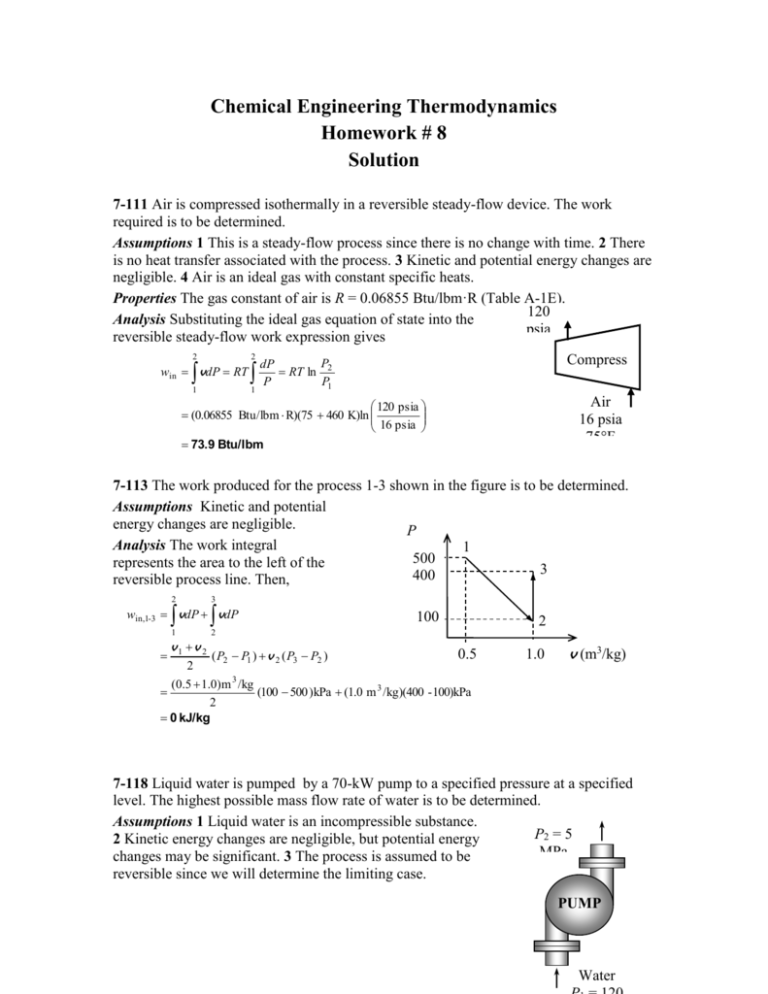
Chemical Engineering Thermodynamics Homework # 8 Solution 7-111 Air is compressed isothermally in a reversible steady-flow device. The work required is to be determined. Assumptions 1 This is a steady-flow process since there is no change with time. 2 There is no heat transfer associated with the process. 3 Kinetic and potential energy changes are negligible. 4 Air is an ideal gas with constant specific heats. Properties The gas constant of air is R = 0.06855 Btu/lbm·R (Table A-1E). 120 Analysis Substituting the ideal gas equation of state into the psia reversible steady-flow work expression gives 75°F 2 2 Compress P dP win vdP RT RT ln 2 or P P1 1 1 Air 16 psia 75°F 120 psia (0.06855 Btu/lbm R)(75 460 K)ln 16 psia 73.9 Btu/lbm 7-113 The work produced for the process 1-3 shown in the figure is to be determined. Assumptions Kinetic and potential energy changes are negligible. P Analysis The work integral 1 (kPa) 500 represents the area to the left of the 3 400 reversible process line. Then, 2 3 win,1-3 vdP vdP 1 v1 v 2 100 2 2 0.5 ( P2 P1 ) v 2 ( P3 P2 ) 2 (0.5 1.0)m 3 /kg (100 500 )kPa (1.0 m 3 /kg)(400 - 100)kPa 2 0 kJ/kg 1.0 v (m3/kg) 7-118 Liquid water is pumped by a 70-kW pump to a specified pressure at a specified level. The highest possible mass flow rate of water is to be determined. Assumptions 1 Liquid water is an incompressible substance. P2 = 5 2 Kinetic energy changes are negligible, but potential energy MPa changes may be significant. 3 The process is assumed to be reversible since we will determine the limiting case. PUMP Water Properties The specific volume of liquid water is given to be v1 = 0.001 m3/kg. Analysis The highest mass flow rate will be realized when the entire process is reversible. Thus it is determined from the reversible steady-flow work relation for a liquid, Win m 2 1 v dP ke0 pe m v P2 P1 g z2 z1 Thus, 1 kJ 1 kJ/kg (9.8 m/s 2 )(10 m) 7 kJ/s m (0.001 m3/kg )(5000 120 ) kPa 3 1000 m 2 /s2 1 kPa m It yields 1.41 kg/s m 7-119E Helium gas is compressed from a specified state to a specified pressure at a specified rate. The power input to the compressor is to be determined for the cases of isentropic, polytropic, isothermal, and two-stage compression. Assumptions 1 Helium is an ideal gas with constant specific heats. 2 The process is reversible. 3 Kinetic and potential energy changes are negligible. Properties The gas constant of helium is R = 2.6805 2 psia.ft3/lbm.R = 0.4961 Btu/lbm.R. The specific heat ratio of helium is k = 1.667 (Table A-2E). · Analysis The mass flow rate of helium is W He P V 14 psia 5 ft 3 /s m 1 1 RT1 2.6805 psia ft 3 /lbm R 530 R (a) Isentropic compression with k = 1.667: 0.0493 lbm/s 5 ft3/s k 1 / k 1 kRT1 P2 Wcomp, in m 1 k 1 P1 0.667/1.667 1.667 0.4961 Btu/lbm R 530 R 120 psia 0.0493 lbm/s 1 1.667 1 14 psia 44.11 Btu/s 62.4 hp since 1 hp = 0.7068 Btu/s (b) Polytropic compression with n = 1.2: n 1 / n nRT1 P2 Wcomp, in m 1 n 1 P1 0.2/1.2 1.2 0.4961 Btu/lbm R 530 R 120 psia 0.0493 lbm/s 1 1.2 1 14 psia 33.47 Btu/s 47.3 hp since 1 hp = 0.7068 Btu/s (c) Isothermal compression: P 120 psia Wcomp, in m RT ln 2 0.0493 lbm/s 0.4961 Btu/lbm R 530 R ln 27.83 Btu/s 39.4 hp P1 14 psia (d) Ideal two-stage compression with intercooling (n = 1.2): In this case, the pressure ratio across each stage is the same, and its value is determined from Px P1P2 14 psia 120 psia 41.0 psia The compressor work across each stage is also the same, thus total compressor work is twice the compression work for a single stage: n 1 / n nRT1 Px Wcomp, in 2m wcomp, I 2m 1 n 1 P1 0.2/1.2 1.2 0.4961 Btu/lbm R 530 R 41 psia 20.0493 lbm/s 1 1.2 1 14 psia 30.52 Btu/s 43.2 hp since 1 hp = 0.7068 Btu/s 7-139E Argon enters an adiabatic compressor with an isentropic efficiency of 80% at a specified state, and leaves at a specified pressure. The exit temperature of argon and the work input to the compressor are to be determined. Assumptions 1 This is a steady-flow process since there is no change with time. 2 Potential energy changes are negligible. 3 The device is adiabatic and thus heat transfer is negligible. 4 Argon is an ideal gas with constant specific heats. Properties The specific heat ratio of argon is 2 k = 1.667. The constant pressure specific heat of argon is cp = 0.1253 Btu/lbm.R (Table A-2E). Ar C = Analysis (a) The isentropic exit temperature T2s is determined from 80% k 1 / k 0.667/1.667 P T2 s T1 2 s P1 200 psia 550 R 20 psia 1381.9 R The actual kinetic energy change during this process is kea V22 V12 240 ft/s2 60 ft/s2 2 2 1 Btu/lbm 25,037 ft 2 /s 2 1 1.08 Btu/lbm The effect of kinetic energy on isentropic efficiency is very small. Therefore, we can take the kinetic energy changes for the actual and isentropic cases to be same in efficiency calculations. From the isentropic efficiency relation, including the effect of kinetic energy, C ws (h2 s h1 ) ke c p T2 s T1 kes 0.1253 1381 .9 550 1.08 0.8 wa (h2a h1 ) ke c p T2a T1 kea 0.1253 T2a 550 1.08 It yields T2a = 1592 R (b) There is only one inlet and one exit, and thus m 1 m 2 m . We take the actual compressor as the system, which is a control volume since mass crosses the boundary. The energy balance for this steady-flow system can be expressed as E E out in Rate of net energy transfer by heat, work, and mass E system0 (steady) 0 Rate of change in internal,kinetic, potential,etc. energies E in E out Wa,in m (h1 V12 / 2) m (h2 + V22 /2) (since Q pe 0) V 2 V12 Wa,in m h2 h1 2 wa,in h2 h1 Δke 2 Substituting, the work input to the compressor is determined to be wa,in 0.1253 Btu/lbm R 1592 550 R 1.08 Btu/lbm 131.6 Btu/lbm 7-146 Each member of a family of four take a 5-min shower every day. The amount of entropy generated by this family per year is to be determined. Assumptions 1 Steady operating conditions exist. 2 The kinetic and potential energies are negligible. 3 Heat losses from the pipes and the mixing section are negligible and thus 4 Showers operate at maximum flow conditions during the entire shower. 5 Each member of the household takes a 5-min shower every day. 6 Water is an incompressible substance with constant properties at room temperature. 7 The efficiency of the electric water heater is 100%. Properties The density and specific heat of water at room temperature are = 1 kg/L = 1000 kg/3 and c = 4.18 kJ/kg.C (Table A-3). Analysis The mass flow rate of water at the shower head is Mixtur = V = (1kg/L)(12L/min) = 12 kg/min m e The mass balance for the mixing chamber 3 Cold Hot can be expressed in the rate form as water water 1 2 m in m out m system0 (steady) 0 m in m out m 1 m 2 m 3 where the subscript 1 denotes the cold water stream, 2 the hot water stream, and 3 the mixture. The rate of entropy generation during this process can be determined by applying the rate form of the entropy balance on a system that includes the electric water heater and the mixing chamber (the T-elbow). Noting that there is no entropy transfer associated with work transfer (electricity) and there is no heat transfer, the entropy balance for this steady-flow system can be expressed as Sin Sout Rate of net entropy transfer by heat and mass Sgen Rate of entropy generation Ssystem0 (steady) Rate of change of entropy m 1s1 m 2 s2 m 3s3 Sgen 0 (since Q 0 and work is entropy free) Sgen m 3s3 m 1s1 m 2 s2 Noting from mass balance that m 1 m 2 m 3 and s2 = s1 since hot water enters the system at the same temperature as the cold water, the rate of entropy generation is determined to be T Sgen m 3s3 (m 1 m 2 ) s1 m 3 ( s3 s1 ) m 3c p ln 3 T1 (12 kg/min)(4. 18 kJ/kg.K)ln 42 + 273 4.495 kJ/min.K 15 + 273 Noting that 4 people take a 5-min shower every day, the amount of entropy generated per year is Sgen ( Sgen )t ( No. of people)(No. of days) (4.495 kJ/min.K)( 5 min/person day)(4 persons)(365 days/year) = 32,814 kJ/K (per year) Discussion The value above represents the entropy generated within the water heater and the T-elbow in the absence of any heat losses. It does not include the entropy generated as the shower water at 42C is discarded or cooled to the outdoor temperature. Also, an entropy balance on the mixing chamber alone (hot water entering at 55C instead of 15C) will exclude the entropy generated within the water heater. 7-155 Nitrogen is compressed by an adiabatic compressor. The entropy generation for this process is to be determined. Assumptions 1 Steady operating conditions exist. 2 The compressor is well-insulated so that heat loss to the surroundings is negligible. 3 Changes in the kinetic and potential energies are negligible. 4 Nitrogen is an ideal gas with constant specific heats. Properties The specific heat of nitrogen at the average temperature of (17+227)/2=122C = 395 K is cp = 1.044 kJ/kgK (Table A-2b). Analysis The rate of entropy generation in the pipe is determined by applying the rate form of the entropy balance on the compressor: S in S out Rate of net entropy transfer by heat and mass S gen Rate of entropy generation S system0 (steady) Rate of change of entropy m 1 s1 m 2 s 2 S gen 0 (since Q 0) S gen m ( s 2 s1 ) Substituting per unit mass of the oxygen, s gen s 2 s1 c p ln Compresso r Air 100 kPa 17C T2 P R ln 2 T1 P1 (1.044 kJ/kg K)ln 600 kPa 227C (227 273) K 600 kPa (0.2968 kJ/kg K)ln (17 273) K 100 kPa 0.0369 kJ/kg K 7-168 Liquid water is heated in a chamber by mixing it with superheated steam. For a specified mixing temperature, the mass flow rate of the steam and the rate of entropy generation are to be determined. Assumptions 1 This is a steady-flow process since there is no change with time. 2 Kinetic and potential energy changes are negligible. 3 There are no work interactions. Properties Noting that T < Tsat @ 200 kPa = 120.21C, the cold water and the exit mixture streams exist as a compressed liquid, which can be approximated as a saturated liquid at the given temperature. From Tables A-4 through A-6, 1200 kJ/min P1 200 kPa h1 h f @ 20 C 83.91 kJ/kg T1 20 C s s 0.2965 kJ/kg K f @ 20 C 1 P2 200 kPa h2 2769 .1 kJ/kg T2 15 0C s 2 7.2810 kJ/kg K P3 200 kPa h3 h f @60 C 251.18 kJ/kg s s 0.8313 kJ/kg K T3 60 C f @ 60 C 3 1 20C 2.5 kg/s MIXING CHAMBER 2 150 C 200 kPa 60 C 3 Analysis (a) We take the mixing chamber as the system, which is a control volume. The mass and energy balances for this steady-flow system can be expressed in the rate form as 1 m 2 m 3 Mass balance: m in m out Esystem0 (steady) 0 m Energy balance: E E out in Rate of net energy transfer by heat, work, and mass E system0 (steady) 0 Rate of change in internal,kinetic, potential,etc. energies E in E out m 1h1 m 2 h2 Q out m 3h3 Combining the two relations gives Qout m1h1 m 2h2 m1 m 2 h3 m1h1 h3 m 2 h2 h3 Solving for and substituting, the mass flow rate of the superheated steam is determined to be m 2 Q out m 1 h1 h3 (1200/60 kJ/s) 2.5 kg/s 83.91 251 .18 kJ/kg 0.166 kg/s h2 h3 (2769 .1 251 .18 )kJ/kg Also, m 3 m 1 m 2 2.5 0.166 2.666 kg/s (b) The rate of total entropy generation during this process is determined by applying the entropy balance on an extended system that includes the mixing chamber and its immediate surroundings so that the boundary temperature of the extended system is 25C at all times. It gives Sin Sout Rate of net entropy transfer by heat and mass m 1s1 m 2 s2 m 3s3 Sgen Rate of entropy generation Ssystem0 0 Rate of change of entropy Q out Sgen 0 Tb,surr Substituting, the rate of entropy generation during this process is determined to be Q Sgen m 3s3 m 2 s2 m 1s1 out Tb,surr 2.666 kg/s 0.8313 kJ/kg K 0.166 kg/s 7.2810 kJ/kg K (1200 / 60 kJ/s) 2.5 kg/s 0.2965 kJ/kg K 298 K 0.333 kW/K
