Solution
advertisement
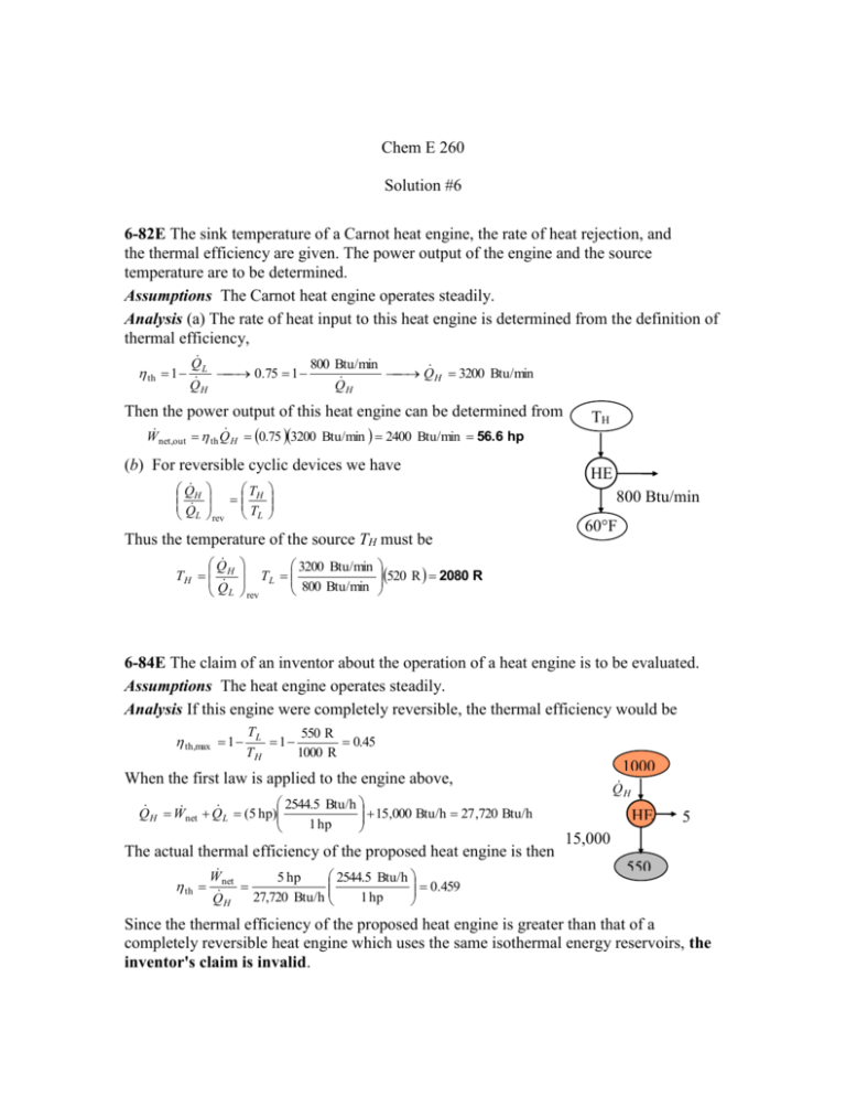
Chem E 260 Solution #6 6-82E The sink temperature of a Carnot heat engine, the rate of heat rejection, and the thermal efficiency are given. The power output of the engine and the source temperature are to be determined. Assumptions The Carnot heat engine operates steadily. Analysis (a) The rate of heat input to this heat engine is determined from the definition of thermal efficiency, th 1 Q L 800 Btu/min 0.75 1 Q H 3200 Btu/min QH Q H Then the power output of this heat engine can be determined from W net,out th Q H 0.75 3200 Btu/min 2400 Btu/min 56.6 hp (b) For reversible cyclic devices we have Q H Q L T H rev TL 3200 Btu/min TL 800 Btu/min rev HE 800 Btu/min Thus the temperature of the source TH must be Q TH H Q L TH 60°F 520 R 2080 R 6-84E The claim of an inventor about the operation of a heat engine is to be evaluated. Assumptions The heat engine operates steadily. Analysis If this engine were completely reversible, the thermal efficiency would be th,max 1 TL 550 R 1 0.45 TH 1000 R When the first law is applied to the engine above, 2544.5 Btu/h 15,000 Btu/h 27 ,720 Btu/h Q H W net Q L (5 hp) 1 hp 15,000 The actual thermal efficiency of the proposed heat engine is then Btu/h th W 2544.5 Btu/h 5 hp 0.459 net 27,720 Btu/h 1 hp QH 1000 Q R H HE 5 hp 550 R Since the thermal efficiency of the proposed heat engine is greater than that of a completely reversible heat engine which uses the same isothermal energy reservoirs, the inventor's claim is invalid. 6-97 The rate of cooling provided by a reversible refrigerator with specified reservoir temperatures is to be determined. Assumptions The refrigerator operates steadily. 300 K Analysis The COP of this reversible refrigerator is COP R, max TL 250 K 5 TH TL 300 K 250 K Rearranging the definition of the refrigerator coefficient of performance gives Q H R 10 kW Q L Q L COP R, max W net,in (5)(10 kW) 50 kW 250 K 6-109E A heat pump maintains a house at a specified temperature. The rate of heat loss of the house is given. The minimum power inputs required for different source temperatures are to be determined. Assumptions The heat pump operates steadily. Analysis (a) The power input to a heat pump will be a minimum when the heat pump operates in a reversible manner. If the outdoor air at 25°F is used as the heat source, the COP of the heat pump and the required power input are determined to be COP HP,max COP HP,rev 1 1 TL / TH 1 10.15 1 25 460 R / 78 460 R House 78F 55,000 Btu/h and Wnet,in,min Q H 55,000 Btu/h 1 hp 2.13 hp COP HP,max 10.15 2545 Btu/h (b) If the well-water at 50°F is used as the heat source, the COP of the heat pump and the required power input are determined to be COPHP,max COPHP,rev HP 25F or 50F 1 1 19.2 1 TL / TH 1 50 460 R / 78 460 R and Wnet,in,min Q H 55,000 Btu/h 1 hp 1.13 hp COP HP,max 19.2 2545 Btu/h 7-25 Heat is transferred directly from an energy-source reservoir to an energy-sink. The entropy change of the two reservoirs is to be calculated and it is to be determined if the increase of entropy principle is satisfied. Assumptions The reservoirs operate steadily. Analysis The entropy change of the source and sink is given by S Q H Q L 100 kJ 100 kJ 0.0833 kJ/K TH TL 1200 K 600 K Since the entropy of everything involved in this process has increased, this transfer of heat is possible. 7-31 R-134a enters an evaporator as a saturated liquid-vapor at a specified pressure. Heat is transferred to the refrigerant from the cooled space, and the liquid is vaporized. The entropy change of the refrigerant, the entropy change of the cooled space, and the total entropy change for this process are to be determined. Assumptions 1 Both the refrigerant and the cooled space involve no internal irreversibilities such as friction. 2 Any temperature change occurs within the wall of the tube, and thus both the refrigerant and the cooled space remain isothermal during this process. Thus it is an isothermal, internally reversible process. Analysis Noting that both the refrigerant and the cooled space undergo reversible isothermal processes, the entropy change for them can be determined from S Q T (a) The pressure of the refrigerant is maintained constant. Therefore, the temperature of the refrigerant also remains constant at the saturation value, (Table A-12) T Tsat@160 kPa 15.6C 257.4 K Then, Srefrigeran t Qrefrigeran t,in Trefrigeran t 180 kJ 0.699 kJ/K 257.4 K R-134a 160 kPa 180 kJ (b) Similarly, S space Qspace,out Tspace 180 kJ 0.672 kJ/K 268 K 5C (c) The total entropy change of the process is Sgen Stotal Srefrigeran t Sspace 0.699 0.672 0.027 kJ/K 7-37 Water is compressed in a compressor during which the entropy remains constant. The final temperature and enthalpy are to be determined. Analysis The initial state is superheated vapor and the entropy is T1 160 C h1 2800.7 kJ/kg (from EES) P1 35 kPa s1 8.1531 kJ/kg K Note that the properties can also be determined from Table A-6 by interpolation but the values will not be as accurate as those by EES. The final state is superheated vapor and the properties are (Table A-6) T 2 1 s P2 300 kPa T2 440.5 C s 2 s1 8.1531 kJ/kg K h2 3361.0 kJ/kg 7-58 Steam is expanded in an isentropic turbine. The work produced is to be determined. Assumptions 1 This is a steady-flow process since there is no change with time. 2 The process is isentropic (i.e., reversible-adiabatic). Analysis There is only one inlet and one exit, and thus m1 m 2 m . We take the turbine as the system, which is a control volume since mass crosses the boundary. The energy balance for this steady-flow system can be expressed in the rate form as 2 MPa E E E system0 (steady) 0 inout 360°C Rate of net energy transfer Rate of change in internal,kinetic, by heat, work, and mass potential,etc. energies E in E out Turbin e m h1 m h2 W out W m (h h ) out 1 2 T The inlet state properties are 100 kPa P1 2 MPa h1 3159 .9 kJ/kg (Table A - 6) T1 360 C s1 6.9938 kJ/kg K 2 MPa For this isentropic process, the final state properties are (Table A-5) 100 kPa s2 s f 6.9938 1.3028 P2 100 kPa 0.9397 x2 s 6.0562 fg s 2 s1 6.9938 kJ/kg K h2 h f x 2 h fg 417 .51 (0.9397 )( 2257 .5) 2538 .9 kJ/kg Substituting, wout h1 h2 (3159 .9 2538 .9) kJ/kg 621.0 kJ/kg 1 2 s


