PowerPoint file
advertisement
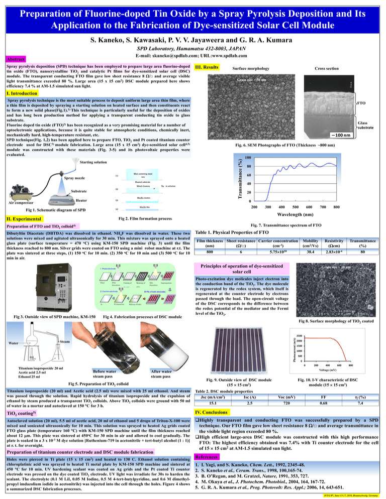
Preparation of Fluorine-doped Tin Oxide by a Spray Pyrolysis Deposition and Its Application to the Fabrication of Dye-sensitized Solar Cell Module S. Kaneko, S. Kawasaki, P. V. V. Jayaweera and G. R. A. Kumara SPD Laboratory, Hamamatsu 432-8003, JAPAN E-mail: skaneko@spdlab.com; URL:www.spdlab.com Abstract Spray pyrolysis deposition (SPD) technique has been employed to prepare large area fluorine-doped tin oxide (FTO), nanocrystalline TiO2 and catalytic Pt films for dye-sensitized solar cell (DSC) module. The transparent conducting FTO film gave low sheet resistance 8 /□ and average visible light transmittance exceeded 80 %. Large area (15 x 15 cm2) DSC module prepared here shows efficiency 7.4 % at AM-1.5 simulated sun light. III. Results Surface morphology Cross section Grain size ~ 50 nm I. Introduction Spray pyrolysis technique is the most suitable process to deposit uniform large area thin film, where a thin film is deposited by spraying a starting solution on heated surface and then constituents react to form a new solid phase(Fig.1).1) This technique is particularly useful for the deposition of oxides and has long been production method for applying a transparent conducting tin oxide to glass substrate. Fluorine doped tin oxide (FTO)2) has been recognized as a very promising material for a number of optoelectronic applications, because it is quite stable for atmospheric conditions, chemically inert, mechanically hard, high-temperature resistant, etc. SPD technique(Fig. 1,2) has been applied here to prepare FTO, TiO2 and Pt coated titanium counter electrode used for DSC3) module fabrication. Large area (15 x 15 cm2) dye-sensitized solar cell4,5) module was constructed with these materials (Fig. 3-5) and its photovoltaic properties were evaluated. FTO Glass substrate 100 nm Transmittance (%) Fig. 6. SEM Photographs of FTO (Thickness ~800 nm) Starting solution Mist containing metal (1) Spray nozzle ions Heated substrate Xn in solution Metal clusters (2) Substrate MmXn clusters Heater Air compressor (3) 80 60 40 20 0 200 MmXn film (4) Fig 1. Schematic diagram of SPD 100 300 400 500 600 700 800 Wavelength (nm) Fig 2. Film formation process II. Experimental Fig. 7. Transmittance spectrum of FTO Preparation of FTO and TiO2 colloid4) Dibutyltin Diacetate (DBTDA) was dissolved in ethanol. NH4F was dissolved in water. These two solutions were mixed and agitated ultrasonically for 30 min. This mixture was sprayed onto a heated glass plate (surface temperature = 470 oC) using KM-150 SPD machine (Fig. 3) until the film thickness reached to 800 nm. Silver grids were coated on FTO using a mini robot machine at r.t. The plate was sintered at three steps, (1) 150 oC for 10 min. (2) 350 oC for 10 min and (3) 500 oC for 10 min in air. Table 1. Physical Properties of FTO Film thickness Sheet resistance Carrier concentration (nm) (cm-3) (/□) 800 6 5.751020 Principles of operation of dye-sensitized solar cell Ⅰ Photo-electrode Glass FTO deposition substrate Coating of Masking of Ag grid FTO Ⅱ Counter-electrode Pt deposition Ti TiO2 deposition Impregnation of dye onto TiO2 Ⅲ Pile of both electrodes Making of holes Substrate Fig 3. Outside view of SPD machine, KM-150 Mobility (cm2/Vs) 38.4 Fig 4. Fabrication processes of DSC module Resistivity (cm) 2.8310-4 Transmittance (%) 80 Grain size ~ 10 nm Photo-excitation dye molicules inject electron into the conduction band of the TiO2. The dye molecule is regenerated by the redox system, which itself is regenerated at the counter electrode by electrons passed through the load. The open-circuit voltage of the DSC corresponds to the difference between the redox potential of the mediator and the Fermi level of the TiO2. Fig 8. Surface morphology of TiO2 coated Photocurrent (mA) 2500 Steam Water 2000 1500 1000 500 0 0 Titanium isopropoxide 20 ml Acetic acid 2.5 ml Ethanol 25 ml Before water steam pass 200 400 600 800 Voltage (mV) After water steam pass Fig. 9. Outside view of DSC module (15 15 cm2) Fig 5. Preparation of TiO2 colloid Fig. 10. I-V characteristic of DSC module (15 15 cm2) Titanium isopropoxide (20 ml) and Acetic acid (2.5 ml) were mixed with 25 ml ethanol. And steam was passed through the solution. Rapid hydrolysis of titanium isopropoxide and the expulsion of ethanol by steam produced a transparent TiO2 colloids. Above TiO2 colloids were ground with 50 ml of water in a mortar and autoclaved at 150 C for 3 h. Table 2. DSC module properties Jsc (mA/cm2) Isc (A) 15.1 2.5 TiO2 coating5) IV. Conclusions Autoclaved solution (20 ml), 5.5 ml of acetic acid, 20 ml of ethanol and 5 drops of Triton-X-100 were mixed and sonicated ultrasonically for 10 min. This solution was sprayed to heated Ag grids coated FTO glass plate (temperature 160 C) with KM-150 SPD machine until the film thickness reached about 12 m. This plate was sintered at 450oC for 30 min in air and allowed to cool gradually. The plate is soaked in a 3 x 10⁻³ M dye solution [Ruthenium-719 in acetonitrile + tert-butyl alcohol (1 : 1)] at r. t. for overnight. Highly transparent and conducting FTO was successfully prepared by a SPD technique. Our FTO film gave low sheet resistance 8 /□ and average transmittance in the visible light region exceeded 80 %. High efficient large-area DSC module was constructed with this high performance FTO: The highest efficiency obtained was 7.4% with Ti counter electrode for the cell of 15 15 cm2 at AM-1.5 simulated sun light. Preparation of titanium counter electrode and DSC module fabrication cm2) Holes were pierced in Ti plate (15 x 15 and heated to 130 C. Ethanol solution containing chloroplatinic acid was sprayed to heated Ti metal plate by KM-150 SPD machine and sintered at 450 C for 10 min. UV hardening sealant was coated on Ag grids and the Pt coated Ti counter electrode was pressed on the dye coated TiO2 electrode. UV light was irradiate for 30s to harden the sealant. The electrolyte (0.1 M LiI, 0.05 M Iodine, 0.5 M 4-tert-butylpyridine, and 0.6 M dimethylpropyl imdazolium iodide in acetonitrile) was injected into the cell through the holes. Figure 4 shows a summarized DSC fabrication processes. Voc (mV) 720 FF 0.68 (%) 7.4 References 1. 2. 3. 4. 5. I. Yagi, and S. Kaneko, Chem. Lett., 1992, 2345-48. S. Kaneko et al., Ceram. Trans., 1998, 100,165-74. B. O’Regan, and M. Gratzel, Nature, 1991, 353, 727. M. Okuya et al., J. Photochem. Photobiol., 2004, 164, 167-72. G. R. A. Kumara et al., Prog. Photovolt: Res. Appl.; 2006, 14, 643-651. ICCG 8th, June 13-17, 2010, Braunschweig, Germany

