An Overview of Detectors
advertisement
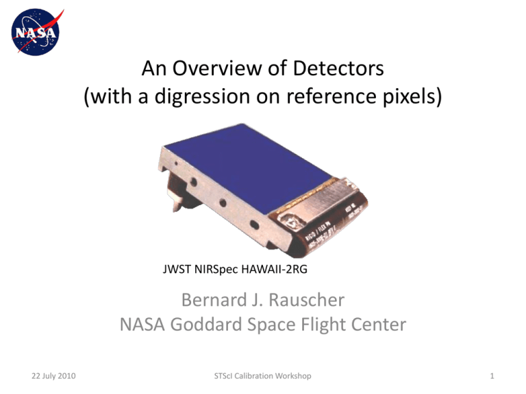
An Overview of Detectors (with a digression on reference pixels) JWST NIRSpec HAWAII-2RG Bernard J. Rauscher NASA Goddard Space Flight Center 22 July 2010 STScI Calibration Workshop 1 Introduction • After the diameter of the primary mirror, no component affects the performance of an observatory more than the detectors • Detectors imprint a signature (e.g. dead pixels, hot pixels, QE variations etc.) onto the data • Calibrating out this signature is critical to getting the most out of these observatories • Need to understand how detectors function and why specific signatures occur • In this talk, I present an introduction to detectors with an emphasis on JWST’s HAWAII-2RG (H2RG) sensor chip assemblies (SCA) 22 July 2010 STScI Calibration Workshop 2 Common detector types for the visible through mid-IR Hybrid detector arrays CCD • Photon collection separated from readout – – • Optimized detector layer collects charge Optimized readout integrated circuit senses charge in place (it does not move like in a CCD) Multiple non-destructive reads typically used to beat down read noise and integrate through cosmic ray hits Mid-IR array Near-IR array WFC3 CCDs • • Intrinsic Si photoconcuctor • Photons collected and charge read out in same piece of silicon • • • During readout, charge physically moves from one pixel to the next Usual readout is correlated double sampling Because charge moves, onchip binning is possible 22 July 2010 JWST NIRSpec H2RG • • • Intrinsic HgCdTe or InSb photoconductor NICMOS, IRAC, WFC3, JWST NIR instruments STScI Calibration Workshop • • • JWST MIRI Extrinsic (intentionally doped) Si:As photoconducor (other dopants are possible for longer wavelength response) IRAC and JWST/MIRI 3 Photon detection in semi-conductors • • Photons are absorbed in the semiconductor creating electron/hole pairs For photon energies less than the bandgap, the photo-conductor does not respond to light unless it has been doped (e.g. MIRI’s detectors) – • For photon energies greater than about 1/3rd of the bandgap (very blue light), multiple carrier creation becomes increasingly likely – – • No calibration issues –light is just not detected “ptype” “ntype” Probable calibration issue for JWST. Both NIRSpec and FGS use 5 micron cutoff detectors at 600 nm RQE > DQE! To see how MIRI’s Si:As detectors work, compare the diagram of crystal structure (above) with the band gap diagrams (below). To free an electron in intrinsic material (1) requires a certain energy indicated by the band gap. It takes less energy to free charge carriers from impurities (2) and (3). 22 July 2010 STScI Calibration Workshop 4 Rieke, G.H. 2010, Elixir School How a JWST near-IR array works Readout Integrated Circuit (ROIC) Simplified structure of a hybrid IR array detector. In real arrays, there is often an epoxy backfill between the indium bumps. 22 July 2010 STScI Calibration Workshop 5 For WFC3 and JWST, the HgCdTe is graded to sweep charge (actually holes) to the depletion region Detector Band Diagram p-HgCdTe (implant) H2RG ROIC Surface Passivation In bump interconnect Cap Surface Passivation HgCdTe Buffer Cap n-HgCdTe HgCdTe Buffer CdZnTe substrate (removed) Conduction band electrons p-HgCdTe (implant) n-HgCdTe MBE Growth Direction CdZnTe substrate (removed) HAWAII-2RG pixel architecture. Photons enter from the bottom. AR coating goes on at the dotted green line after the substrate has been removed 22 July 2010 STScI Calibration Workshop 6 What happens in a JWST NIR pixel? Outside the depletion region, E fields are weaker and charge can diffuse between pixels QE depends on wavelength. Blue light is absorbed near the surface and red light is absorbed deep in the detector If an anomaly is strongest in the blue, it might be a surface effect. If it is strongest in the red, it might affect deeper detector layers e- e+ photon 22 July 2010 STScI Calibration Workshop Holes are collected in the depletion region where p-type HgCdTe meets n-type HgCdTe and electrical fields (arrows) are strong 7 JWST’s H2RGs are part of the Teledyne HxRG family H: HAWAII: HgCdTe Astronomical Wide Area Infrared Imager x: Number of 1024 (or 1K) pixel blocks in x and y-dimensions R: Reference pixels G: Guide window capability Substrate-removed HgCdTe for simultaneous visible & infrared observation Hybrid Visible Silicon Imager; Si-PIN (HyViSI) 8 Pixel Pitch # of Outputs Institutions, Observatories, and Programs Using HxRG Arrays (mm) Name Format (# of Pixel) H1RG 1024 × 1024 18 H2RG 2048 × 2048 18 H4RG-10 4096 × 4096 10 H4RG-15 4096 × 4096 15 Wide-field Infrared Survey Explorer (WISE) Orbiting Carbon Observatory (OCO) Development Programs in Astronomy & Earth Science James Webb Space Telescope (JWST) - NIRCam, NIRSpec, FGS Joint Dark Energy Mission (JDEM) Astronomy institutions and observatories: Calar Alto, Caltech, CFHT, ESO, 1, 4, 32 ESTEC, Gemini, GSFC, IRTF, ISRO, IUCAA, JHU-APL, Keck, LBNL, LMU, MIT, MPIA, MPS, OCIW, Penn State, RIT, SALT, SAO, Subaru, TATA, U. Arizona, UCLA, UC Berkeley, U. Hawaii, U. Rochester, U. Toronto, U. Wisconsin Space surveillance applications 1, 4, 16, 32, Joint Milli-Arcsecond Pathfinder Survey (J-MAPS) 64 Development Programs in Astronomy 1, 2, 16 1, 4, 16, 32, In Development, first on sky telescope test in 2011 64 HxRG Pixel in the ROIC Green: Clocks Purple: Bias voltages Output Buffered Output Buffered Output Disable Horizontal Read Bus Output Buffer drain voltage Dsub Reset Clock Detector Substrate Voltage Photovoltaic Detector Column Select Vreset Reset Voltage Read Select Indium Bump Source Follower MOSFET gate Photocharge integrates here Detector Pixel • Cell drain voltage 3-T ROIC Pixel Cell Column Bus Source follower per detector (SFD) architecture is not unique to Teledyne. Raytheon has also used an SFD with their astronomical detector arrays 9 Some calibration “gotcha’s” and where they might originate in the sensor chip assemblies (SCA) Electronic crosstalk Random Telegraph Noise (RTN) Ghosts Open Pixels Inter-Pixel Capacitance (IPC) Hot Pixels Charge diffusion Persistence and latent images Flatfield structure Inter-pixel sensitivity variations (IPS) Flux Dependent Linearity Fringing (only if substrate removal was not complete) Non-linear response (also electronics) 22 July 2010 STScI Calibration Workshop 10 An example of how understanding the device can aid understanding a calibration issue: reciprocity failure Courtesy Bob Hill • For NICMOS, strongest in the blue – Suggests surface trapping is important • According to U. Michigan group, cooling helps – Suggests traps are shallow 22 July 2010 STScI Calibration Workshop 11 Some “gotcha’s” originate in the readout electronics • 1/f noise (more on this later) – Particularly evident with SIDECAR ASIC in JWST ultralow-power & temperature operation – Also seen in ground based controllers • Bars & bands – Happen when one part of the system pulls down the biases for another • Tails – Caused by settling time issues in the readout electronics and harnesses • Pedestal drifts – Caused by unstable biases 22 July 2010 STScI Calibration Workshop 12 Schematic of a MIR IBC Detector 22 July 2010 STScI Calibration Workshop 13 Rieke, G.H. 2010, Elixir School Readout • For CCDs, charge is moved to the output, sensed, and discarded – Nevertheless, noise performance of CCDs is outstanding. JWST’s NIR and MIR arrays do not yet match them • For NIR and MIR arrays, charge is sensed in place by the ROIC – Can use multiple non-destructive reads to average down noise and integrate through cosmic ray hits! – Achieving CCD like noise performance with JWST’s NIR arrays will require new readout approaches (yes, we are working on this!) 22 July 2010 STScI Calibration Workshop 14 How noise averages down with multiple non-destructive reads sread - Read noise per read n – Number of up-the-ramp groups m – Number of frames per group tf – Frame readout time tg – Group time f – Photonic current (includes dark current) • • Model does not include 1/f noise, will under estimate the noise of JWST’s SIDECAR based detector systems somewhat This differs slightly from what is shown in Rauscher et al., PASP, 119, 768 (due to a transcription error while finalizing the manuscript) – Error caught by Massimo Robberto of STScI (Thanks!) – Massimo presents an independent derivation that expands this result somewhat in an internal STScI memo (please speak to Massimo for details) 22 July 2010 STScI Calibration Workshop 15 Richard G. Arendt1, Dale J. Fixsen1, Don Lindler1, Markus Loose2, Samuel H. Moseley1 & Bernard J. Rauscher1 1NASA Goddard Space Flight Center 2Markury Scientific ADVANCED TOPIC: REFERENCE PIXELS 22 July 2010 STScI Calibration Workshop 16 Overview • • • • • • • 1. 2. Performance of 2kx2k Teledyne HAWAII-H2RG detectors and SIDECAR ASICs is key to the success of the JWST mission Broadband imaging is generally background limited. With QE ~ 80%, only incremental improvement still possible Spectroscopy & narrow band imaging are generally detector noise limited –large improvements still possible even with NIRSpec’s 6 erms total noise requirement We have begun a program to analyze the noise characteristics of the NIRSpec detector subsystem, studying the correlations among the detector outputs and with the reference output, as well as the temporal correlations in a given detector section. JWST NIRSpec H2RG sensor chip assembly (SCA) Using the measured characteristics of the noise correlations, we can determine the optimal coefficients for the removal of correlated noise as a function of frequency. By using all available reference sources, and by adding more frequent references, we can potentially reduce the noise by a factor of two We find that there is a frequency dependent gain and a frequency dependent correlation between the regular pixels and the reference pixels and the reference output In this talk we will present a demonstration of the analysis and mitigation techniques, and describe how to improve the next generation of detectors and readout electronics 29 June 2010 SPIE Telescopes & Instruments 17 Principal Components Analysis • • • • Principal components analysis (PCA) puts noise studies on a firm quantitative foundation Computed the covariance matrix of vertical and horizontal cuts across the detector array, as well as in ~ 64 x 64 pixel regions Computed the eigensystem of the covariance matrix and sorted the eigenvectors by descending eigenvalue Major noise components of Flight NIRSpec detector subsystem are 1. 1/f noise 2. Alternating column pattern noise • • These components are highly correlated with available references and can be removed using standard techniques Almost all of the correlation is temporal –there is little difference between pixels 29 June 2010 SPIE Telescopes & Instruments 18 Many references available for removing the extra noise 4 rows of reference pixels along the “bottom” and “top” edges of each detector array 4 columns of reference pixels along the “left” and “right” edges of each detector array A separate reference output that is always available for all pixels HAWAII-2RG Detector Array Regular pixels (used as a reference) because they are vignetted and never see light 29 June 2010 SPIE Telescopes & Instruments 19 AN EXAMPLE OF USING MORE AND BETTER REFERENCES 29 June 2010 SPIE Telescopes & Instruments 20 Raw Test Data • Outputs 1-3 sample the detector array, but singleended (not differential which is the default) • Output 4 samples the reference output • For each frame, power spectra of the timeordered data are calculated for each output. Results averaged over 88 frames of a single ramp. 29 June 2010 Op #1 Op #2 Op #3 Op #4 (REFOUT) Appearance of raw single-ended data. The horizontal banding indicates the presence of highly correlated 1/f noise SPIE Telescopes & Instruments 21 Fourier analysis of the raw data Power Cross Power Cross power is a measure of the power that is correlated between the two data sets (e.g. real output vs. reference output) 29 June 2010 SPIE Telescopes & Instruments 22 Effect of different ways of using the references Traditional JWST Differential s = 13.5 e• • s = 10.8 e- Interleaved References s = 9.6 e- Traditional JWST differential feeds the H2RG’s reference output to the SIDECAR ASIC’s differential inputs Differential w/ Frequency dependent gain digitizes everything in single ended mode. A frequency dependent weighting is applied to the H2RG’s reference output before it is subtracted – – • Differential w/ Freq. Dep. Gain This weighting account for gain difference at low freuqncy And lower degree of correlation at high frequency Interleaved references jump out to read 8 blanked off pixels every 128 pixels. Includes corrections for 1/f and alternating columns 29 June 2010 SPIE Telescopes & Instruments 23 Power at the Nyquist Frequency • • Expanded view of power near and at the Nyquist frequency for one of the detector outputs Symbols show results before and after optimal use of reference pixels and outputs 29 June 2010 SPIE Telescopes & Instruments 24 The Noise Floor: Traditional vs. Optimal The input data in both cases are a set of one hundred 88 frame up-the-ramp sampled darks Traditional CDS σCDS ~ 13.5 e- rms Optimal CDS σCDS ~ 9.6 e- rms Ignore the right hand output. It is looking at the reference output, not photo-sensitive pixels 29 June 2010 SPIE Telescopes & Instruments 25 Future prospects • This work highlights the importance of sampling low-noise references frequently and weighting the references by frequency • In current generation H2RG detector arrays, reference pixels in rows and columns are: (1) too far away and (2) too noisy to suppress 1/f noise • In current generation SIDECAR ASICs, there is no good way to weight the H2RG’s reference output by frequency in the differential input • To be most effective 1. References need to be sampled above the 1/f “knee” frequency 2. References need to be significantly quieter than the regular pixels that they are intended to correct 3. Reference corrections need to take into account possible frequency dependent weighting between the reference signal and the signal that is being corrected • These goals can be met by many different ROIC and readout electronics designs 29 June 2010 SPIE Telescopes & Instruments 26 To sum up: More & Better References • Noise of JWST’s NIR detectors is much better than we thought! • SIDECARs are injecting correlated noise – Can be removed by using more and better references – Almost all the correlation is temporal rather than spatial – Must work in Fourier domain; reference corrections must be frequency weighted • Flight NIRSpec DS has total noise ~ 6 e- rms for 88 up-theramp samples (EXPTIME ~ 900 s) • The techniques describe here should drop that to about 3.5 e- rms without changing the hardware • Work is ongoing to demonstrate these improvements in practice 29 June 2010 SPIE Telescopes & Instruments 27 Summary • In this short talk, I’ve tried to present an overview of common astronomical detectors for the visible through mid-IR – Emphasis on JWST’s HAWAII-2RG near-IR arrays • Briefly discussed some of the anomalies that are expected, and where they originate in hybrid near-IR arrays – Others will no doubt discuss many of these further at this conference • Discussed how using more references more effectively can significantly improve the performance of JWST’s detector limited instruments 22 July 2010 STScI Calibration Workshop 28
