Lecture materials on introduction to Entropy and second law
advertisement
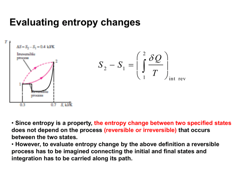
Evaluating entropy changes 2 Q S 2 S1 1 T int rev • Since entropy is a property, the entropy change between two specified states does not depend on the process (reversible or irreversible) that occurs between the two states. • However, to evaluate entropy change by the above definition a reversible process has to be imagined connecting the initial and final states and integration has to be carried along its path. Using entropy change and thermodynamic temperature to graphically interpret the heat supplied in reversible processes Q dS T rev Q rev TdS W rev PdV P T 1 2 S V 2 Q rev TdS 1 2 W rev 1 P dV Showing a Carnot cycle on a T-s diagram Isotherms: horizontal lines Isentropes:vertical lines T 2 1 Application: Carnot engine Qnet,in 4 3 s Isobars and isochores on the T-s diagram for an ideal gas (Sec. 7.9) s s1 ~ c avg v s s1 ~ c avg p T v ln R ln T1 v1 s s1 Isochores: T ~ T exp Isochores: avg 1 cv T P ln R ln T1 P1 ss 1 Isobars: T ~ T exp 1 c avg p T v P s P T P1 T1 v1 vT T 1 T-s diagram of a cycle: try yourself • The Brayton cycle used in a gas turbine engine consists of following steps: – isentropic compression (1-2). – isobaric heat addition (2-3). – isentropic expansion (3-4). – isobaric heat rejection (4-1). Plot this process on a T-s and P-v diagram. Use of the Tds relations in calculating entropy changes On an intensive (per unit mass) basis: dS dU P dV T dS First TdS relation T dH V dP T T ds du T Second TdS relation ds dh T Pdv T vdP T Integrating between initial (1) and the final state (2): 2 s 2 s1 1 2 s 2 s1 1 du 2 T dh T 1 2 1 P dv T vdP T Even though the Tds equations are derived using an internally reversible process, the change in entropy during an irreversible process occuring between the same two equilibrium states can be also calculated using the integrals on the left. Entropy change of liquids/solids (Sec. 7.8) •Liquid/solid can be approximated as incompressible substances (v=constant): i.e. specific volume ( or density) remains constant even when other properties change (dv=0) Internal energy of a solid/liquid is a function of temperature alonecp=cv=c (one specific heat) d u cd T 2 s 2 s1 1 du T 2 1 P dv T 2 s 2 s1 1 from First Tds relation cdT T 2 c 1 dT T T c ln 2 T1 if temperature variation of specific heat (c)can be neglected. For solids/liquids, the isentropic process is also isothermal. Second law for a closed system undergoing a process Clausius inequality: b: boundary Tb=T for an internally reversible process 0 Tb 1 Q Q T T b 1 2 int 2 2 > for irreversible process 1-2 = internally reversible process 1-2 1 2 S 2 S1 ˜ Q 1 Q Tb Q Tb 0 rev S1 S 2 0 Second law for an isolated system 2 S 1 2 S 2 S 1 1 Q T Also, across the boundaries of an isolated system no energy (heat/work) is transferred (by definition) S 1 2 iso lated 0 The universe (any system + its surroundings) can be considered an isolated system. “The total entropy of the universe is increasing.” Second law for an adiabatic process undergone by a closed system 2 S 1 2 S 2 S 1 1 Q T Second law for a system undergoing adiabatic (irreversible/reversible) process (Q=0) S 1 2 0 S 2 S 1 The entropy balance for closed systems 2 S 2 S1 1 entropy change Q Tb S gen entropy generation within the system entropy transfer accompanying ( S gen 0) heat transfer • Sgen>0 if irreversibilities present inside the system • Sgen=0 for no irreversibilities inside the system • The value of Sgen is a measure of the extent of irreversibilities within the system. More irreversibilities Sgen ↑ Entropy generation (Sgen>0) within the system is due to irreversible processes within the system boundary Irreversible processes occurring within the system boundary result in entropy generation. Examples: • Friction (solid-solid, solid-fluid) may be present between parts of the system. • Hot and cold zones may be present within the system which may be interacting irreversibly through heat transfer. • Non-quasi-equilibrium compression/expansion occuring between parts of the system. • Other: mixing between substances having different chemical composition, chemical reaction. Example of entropy generation due to an irreversible process in an isolated system Remove separator Initial state (1) Pf,Tf, (m1+m2) Final state (2) Objective: • To show that the process is irreversible. Isolated system has Q=0 2 S 2 S1 1 Q Tb To show a process is irreversible S gen ) to show Sgen>0 to show S 2 S 1 0 Example (contd.): The final state of the process P1,V1, T, m1 Pf,Tf, (m1+m2) P2,V2, T, m2 High pressure Low pressure Final temperature: ( m 1 m 2 ) C v T f m 1C v T m 2 C v T T f T • From the first law Uf=Ui. • At the final state: . Pf ( m1 m 2 ) RT V1 V 2 m1 m 2 RT m1 RT / P1 m 2 RT / P2 m1 m 2 m1 / P1 m 2 / P2 Example of entropy generation due to an irreversible process in an isolated system P1,,,V1, T, m1 P2,V2, T, m2 High pressure Low pressure Entropy balance Pf,Tf, (m1+m2) ( m 1 m 2 ) C v T f m 1C v T m 2 C v T T f T S isolated S f S i S gen S isolated S f ( S 1 S 2 ) ( m1 m 2 ) s f ( m1 s1 m 2 s 2 ) m1 ( s f s1 ) m 2 ( s f s 2 ) Entropy change of the system is the entropy change of its parts Example of entropy generation due to an irreversible process in an isolated system P1,,,V1, T, m1, Pf,Tf, (m1+m2) P2,V2, T, m2 Second law (entropy balance) S isolated m1 ( s f s1 ) m 2 ( s f s1 ) p pf T 1 s f s1 C p ln R ln R ln p p T 1 f Similarly s f s 2 R ln p2 pf from integration of Tds=dh-vdP Example of entropy generation due to an irreversible process in an isolated system P1,,,V1, T, m1, Pf,T, (m1+m2) P2,V2, T, m2 S gen S 2 S 1 m 1 ( s f s1 ) m 2 ( s f s 2 ) m m p p p1 1 p 2 2 1 2 m1 R ln m 2 R ln R ln (m m ) p p pf 1 2 f f m S gen R ln p1 1 p 2 m2 m1 m 2 m / P m / P 2 2 1 1 ( m1 m 2 ) 1 S gen 0 process is irreversible 1 m1 m2 m m p1 p 2 1 2 ( m 1 m 2 ) R ln m1 m 2 m / P m / P 2 2 1 1 GM HM Calculating work done in a reversible steady flow process • Reversible cycles develop the maximum work. • Reversible cycles consist of reversible processes through each device. • At every stage of the internally reversible process: First law for control volumes – qrev-wrev=dh +d(ke)+d(pe) – q rev Tds – T d s d h vd P • Combining: wrev=-vdP-d(ke)-d(pe) • Integrating: 2 w rev vdP 1 v 2 v1 2 2 2 g ( z 2 z1 ) Graphical representation of reversible steady flow work on a p-v diagram if changes in KE and PE can be neglected (e.g. in turbines, compressor and pumps, but not in nozzles) 2 w rev v d P 1 Reversible steady flow work for a pump (PUMP HANDLES LIQUIDS) w pum p rev 2 vdP 1 Since specific volume of a liquid is nearly independent of pressure: v~v ~v 1 pum p w rev v1 ( p 2 p1 ) 2 w isen pum p (since pump is an adiabatic device) Alternatively pum p w rev w isen pum p h1 ( P1 , ) h2 ( P2 , s 2 s1 ) h1 h2 s similar to compressor In steam power plants, how big is “turbine work out” compared to “pump work in”? v w tu rb in e rev 4 vd P 3 w pum p rev 2 vdP 1 v ( P2 P1 ) Specific volume of vapors are orders of magnitude larger than the specific volume of liquid (e.g. vf' 10-3 m3/kg vg' 2 m3/kg at 100 kPa)) w pum p rev w com pre ss or re v Gas turbine pumps consume a significant part of work developed in turbines to run compressor
![Introduction to Second Law (contd.) [Lecture 5].](http://s2.studylib.net/store/data/005616309_1-e04677ea698eaf2815262e3c7bbb995c-300x300.png)
