Lecture 16 - Transfer Functions
advertisement
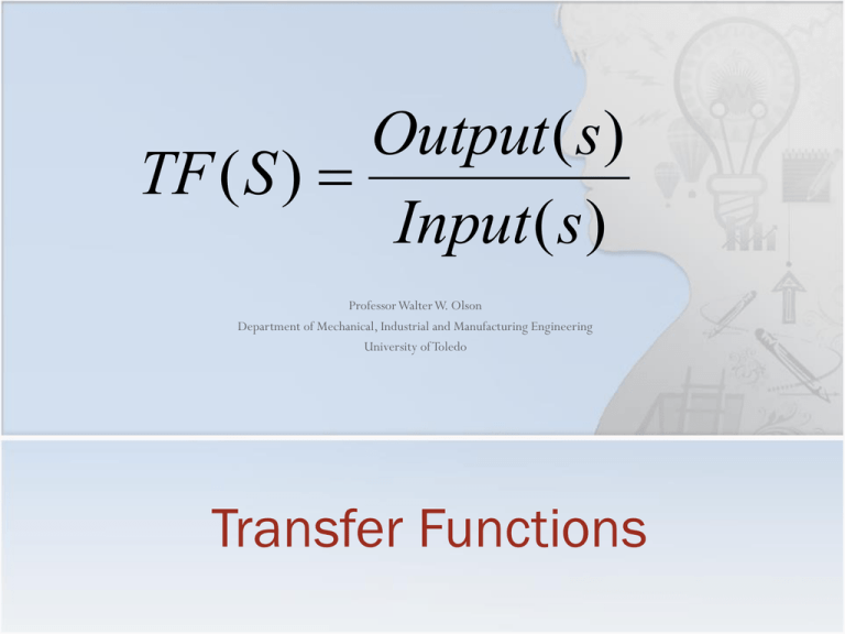
Output ( s ) TF ( S ) Input ( s ) Professor Walter W. Olson Department of Mechanical, Industrial and Manufacturing Engineering University of Toledo Transfer Functions Outline of Today’s Lecture A new way of representing systems Derivation of the gain transfer function Coordinate transformation effects hint: there are none! Development of the Transfer Function from an ODE Gain, Poles and Zeros Observability Can we determine what are the states that produced a certain output? Perhaps Consider the linear system d x Ax Bu dt y Cx Du We say the system is observable if for any time T>0 it is possible to determine the state vector, x(T), through the measurements of the output, y(t), as the result of input, u(t), over the period between t=0 and t=T. Observers / Estimators Input u(t) d x Ax Bu dt y Cx Du Output y(t) Noise State xˆ Observer/Estimator Testing for Observability y (t ) 0 (t )CA0 1 (t )CA 2 (t )CA2 ... n 1 (t )CAn 1 x(0) For x(0) to be uniquely determined, the material in the parens must exist requiring C CA 2 W0 CA C T ... CAn 1 T AC T 2T A C T n 1T ... A C T T to have full rank, thus also being invertible, the common test Wo is called the Observability Matrix Testing for Observability y (t ) 0 (t )CA0 1 (t )CA 2 (t )CA2 ... n 1 (t )CAn 1 x(0) For x(0) to be uniquely determined, the material in the parens must exist requiring C CA 2 W0 CA C T ... CAn 1 T AC T 2T A C T n 1T ... A C T T to have full rank, thus also being invertible, the common test Wo is called the Observability Matrix Example: Inverted Pendulum Determine the observability pf the Segway system with v as the output 0 0 A 0 0 1 0 0 6.405 0 0 0 7.205 0 0 1 0 CA 0 0 6.4046 0 0 0.01837 C = [0 1 0 0] B 0 0.008163 CA2 0 0 0 6.4046 CA3 0 0 46.1459 0 Using the model developed in Lecture 5 for the inverted pendulum 0 0 x 2 2 2 J ml ml g 0 0 v J ( M m ) Mml 2 J ( M m ) Mml 2 F 0 0 1 0 mlg ( M m ) ml 0 0 2 J ( M m ) Mml J ( M m ) Mml 2 M 10kg x v m 80kg y 0 1 0 0 with l 1m J 100kg m 2 / s 2 0 x 0 d v dt 0 0 1 0 0 0 0 1 0. 0. 6.4046 0. Wo 0. 6.4046 0. 0. 0. 0. 0. 46.146 W0 is singular; therefore the system is not observable. We can not see the state variable x as a result of the output! Observable Canonical Form A system is in Observable Canonical Form if it can be put into the form a1 1 0 0 ... a 0 1 0 ... 2 d z ... ... ... ... ... dt an 1 0 0 0 ... an 0 0 0 ... y 1 0 0 ... 0 z Du 0 b1 b 0 2 ... z ... u 1 b n 1 bn 0 Where ai are the coefficients of the characteristic equation I A … u bn S an bn-1 zn S b2 zn-1 an-1 … S a2 … b1 z2 S a1 D z1 -1 S y Observable Canonical Form a1 a 2 d z a3 dt a4 a5 1 0 0 0 0 0 1 0 0 0 0 0 1 0 0 0 b1 b 0 2 0 z b3 u 1 b4 b5 0 y 1 0 0 0 0 z Du The observable matrix has the form 1 a1 W0 a12 a2 3 a 1 2a2 a1 a3 a14 3a2 a12 2a3a1 a22 a4 0 1 a1 a12 a2 a13 2a2 a1 a3 0 0 1 a1 a12 a2 0 0 0 1 a1 0 0 0 0 1 Dual Canonical Forms The Controllable/Reachable canonical form is z1 a1 z 1 2 d z3 0 dt ... ... zn 0 a2 0 1 ... 0 a3 0 0 ... ... 0 1 an z1 1 0 z2 0 0 z3 0 u ... ... 0 0 zn 0 Therefore for system d Ax Bu y Cx dt Ac AoT Bc CoT and Cc Bo T T Ac z Bc u W r Wo The Observable Canonical form is T W rWr 1 y b1 b2 b3 ... bn z Du Cc z Du a1 1 0 0 ... a 0 1 0 ... 2 d z ... ... ... ... ... dt an 1 0 0 0 ... an 0 0 0 ... Ao z Bo u 0 b1 b 0 2 ... z ... u 1 b n 1 bn 0 y 1 0 0 ... 0 z Du Co z Du Ac TAT 1 Bc TB Cc CT 1 A0 Ac T TAT 1 T 1 AT T T T T B0 Cc T CT 1 T 1 C T T C0 Bc T TB B T T T T Input u(t) Output y(t) d x Ax Bu dt y Cx Du Observers / Estimators Noise Observer/Estimator State B + + y C A u x B ++ + + A L C y _ + xˆ Alternative Method of Analysis Up to this point in the course, we have been concerned about the structure of the system and discribed that structure with a state space formulation Now we are going to analyze the system by an alternative method that focuses on the inputs, the outputs and the linkages between system components. The starting point are the system differential equations or difference equations. However this method will characterize the process of a system block by its gain, G(s), and the ratio of the block output to its input. Formally, the transfer function is defined as the ratio of the Laplace transforms of the Input to the Output: TF ( S ) Output ( s ) for s a complex number and the Laplace Variable Input ( s ) System Response From Lecture 11 We derived for u(t ) est where s i t y (t ) Ce x (0) Ce A( t ) Be s d De st At 0 Ce At x (0) Ce At e sI A Be s d De st t 0 Ce At x (0) Ce At ( sI A) 1 e sI A t I B De st Ce At x (0) ( sI A) 1 B C sI A B D e st 1 } } Transient Steady State Transfer function is defined as G ( S ) C sI A B D 1 where s is a complex number Derivation of Gain Consider an input of u(t ) e st e i t e t eit e t cos t i sin t 0 has the effect of damping and determines the damping rate with s i , the eigenvalues of dynamics matrix, A, our solution was x (t ) e At x (0) e A( t ) Be s d e At x (0) e t 0 e At x (0) sI A 1 e sI A t t 0 sI A Be s d 1 B e At x (0) sI A B sI A Be st 1 y (t ) Ce At x (0) sI A B C sI A B e st 1 1 The first term is the transient and dies away if A is stable. If x(0) ( sI A) 1 B then x (t ) ( sI A) 1 Be st ( sI A) 1 Bu(t ) y (t ) (C ( sI A) 1 B D )e st C ( sI A) 1 B D u (t ) thus G ( s ) C ( sI A) 1 B D is the output y in response to input u which we call the transfer function from u to y 1 Example G ( s ) C ( sI A) 1 B D 1 b k m x u(t) mx bx kx u (t ) 0 d x k dt x m x y 1 0 x 1 x 0 b u (t ) x 1 m 1 0 s 0 0 k G ( s ) 1 0 b 0 s 1 m m 1 G( s) b k s2 s m m The general form of the input is u(t ) e st if s 0 then u(t ) e0t 1 a step function m m G ( s ) s 0 for a steady state response y G ( s )u(t ) k k G( s) Example 1 m 2 b k ms bs k s2 s m m From a set of Mathematics Tables, sin t i it iwt (e e ) 2 i it i e and u2 (t ) eit then u(t ) u1 (t ) u1 (t ) 2 2 y (t ) y1 (t ) y2 (t ) G ( s )u1 (t ) s i G ( s )u2 (t ) s i Let u1 (t ) b k G (i ) m u(t) x G (i ) m m i b i k 2 k k 2 m 2 ib 2 m b 2 2 2 m k 2 m 2 ib which is a complex number and can be written in exponential form: G (i ) Mei 1 2 2 2 2 with M km m mb 2 k m 2 b 2 b and tan 1 2 k m G ( i ) can be treated similarly so that M it y (t ) (ie ieit ) M sin t 2 Coordination Transformations x1 d d x Ax Bu z Az Bu dt dt y Cz Du y Cx Du z2 x2 for A TAT 1, B TB and C CT 1 Since the ouput y is unchanged by the transformation z1 y C ( sI A) 1 B D and y C ( sI A) 1 B D y G ( s )u(t ) G ( s )u(t ) G ( s ) G s Thus the Transfer function is invariant under coordinate transformation Linear System Transfer Functions General form of linear time invariant (LTI) system is expressed: (n) n1 n 2 m m1 m2 y a1 y a2 y ... an2 y an1 y an y b0 u b1 u b2 u ... bn2u bn1u bnu For an input of u(t)=est such that the output is y(t)=y(0)est s n a1s n 1 a2 s n 2 ... an 2 s 2 an 1 2 an y0e st b0 s m b1s m 1 b2 s m 2 ... bn 2 s 2 bn 1s bn e st b s bs s a s m y (t ) y (0)e st 0 m 1 1 n 1 n 1 b2 s m 2 ... bn 2 s 2 bn 1s bn a2 s n 2 ... an 2 s 2 an 1 2 an e st The transfer function form is then b0 s m b1s m1 b2 s m2 ... bn 2 s 2 bn 1s bn b( s ) y ( t ) G ( s )u ( t ) G ( s ) n s a1s n 1 a2 s n 2 ... an 2 s 2 an 1 2 an a(s) Note that the transfer function for a simple ODE can be written as the ratio of the coefficients between the left and right sides multiplied by powers of s The order of the system is the highest exponent of s in the denominator. Simple Transfer Functions Differential Equation Transfer Function Name yu s Differentiator yu 1 s 1 s2 1 sa Integrator yu y ay u y 2n y n 2 y u y k pu kd u ki udt 2nd order Integrator 1st order system 1 s 2n s n 2 k p kd s ki s 2 Damped Oscillator PID Controller A Different Method Design a controller that will control the angular position to a given angle, 0 If Va (t ) e i t V0eit V0e st , then from the Convolution Equation (t ) 0e st replacing the variables of the differential equations with this result, we get b KK b d d2 KV0e st st st 0e J JR dt 0e JR dt 2 a a In Lect. 5, we formed the state space rep. from K b d Va ia R dt R b KK b d KVa d 2 a a 2 dt J JR dt JRa d Ki b d a a dt J J dt d 2 b KK b d KVa dt J JRa dt JRa 2 b KK b st KV0e st s s 0e J JR JRa a K JRa 0e st V0e st b KK b s2 s J JR a Output ( s ) (t ) Input ( s ) u (t ) u ( t )V0est K JRa b KK b s2 s J JR a A Different Method Design a controller that will control the angular position to a given angle, 0 d 2 b KK b d KVa dt J JRa dt JRa K JRa G( s) b KK b s2 s J JRa A Different Method Design a controller that will control the angular position to a given angle, 0 R=0.2 J= 10^-5 K=6*10^-5 Kb=5.5*10^-2 b=4*10^-2 gs=(K/(J*R))/(b*s^2/J+K*Kb*s/(J*R)) step(gs) Output ( s ) (t ) Input ( s ) u (t ) u ( t )V0est K JRa b KK b s2 s J JR a We will refer to this as the transfer of the input to the output, or transfer function K JRa G( s) b KK b s2 s J JRa Output ( s ) G ( s ) Input ( s ) Which was the same for the state space Later, we will learn how to control it Gain, Poles and Zeros G ( s ) C ( sI A) 1 B D G (0) D CA1B b( s ) b( s ) K a( s) a( s ) yo bm K uo am The roots of the polynomial in the denominator, a(s), are called the “poles” of the system The poles are associated with the modes of the system and these are the eigenvalues of the dynamics matrix in a state space representation The roots of the polynomial in the numerator, b(s) are called the “zeros” of the system The zeros counteract the effect of a pole at a location The value of G(s) is the zero frequency or steady state gain of the system Summary A new way of representing systems The transfer function G( s) C( sI A)1 B D Derivation of the gain transfer function bs a s Coordinate transformation effects hint: there are none! Development of the Transfer Function from an ODE (n) n1 n 2 m m1 m2 y a1 y a2 y ... an2 y an1 y an y b0 u b1 u b2 u ... bn2u bn1u bnu b0s m b1s m1 b2 s m2 ... bn2 s 2 bn1s bn b( s) G( s ) n n 1 n 2 2 s a1s a2 s ... an2 s an1 2 an a(s) Gain, Poles and Zeros G( s) C ( sI A) 1 B D b( s) b( s) K a( s) a( s) Next: Block Diagrams
