Back-end signal processing
advertisement

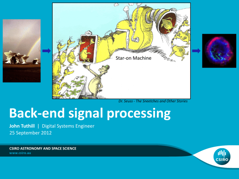
Star-on Machine Dr. Seuss - The Sneetches and Other Stories Back-end signal processing John Tuthill | Digital Systems Engineer 25 September 2012 CSIRO ASTRONOMY AND SPACE SCIENCE Outline • What is “back-end signal processing” • FX vs XF correlators • Filterbanks • Sampling and ADCs • CABB and ASKAP digital back-ends • Calculation engines • Further reading 2 | Back-End Signal Processing | John Tuthill Back-end processing for Synthesis Imaging E f r1 f R R Electric field at the remote source propagated to the observing points E f r 2 r1 X r2 down- X conversion Spatial Coherence function or “visibilities” V f r1 , r 2 E f r1 E f r 2 Intensity distribution of the source I f l , m V f u , v e i 2 ul vm .dudv Sampling Back-End Digital Signal Processing Correlator 3 | Back-End Signal Processing | John Tuthill Imaging: calibration, 2D FFT, deconvolution Image: Shaun Amy Spectral Channelisation V f r1 , r 2 E f r1 E f r 2 • Interested in obtaining the cross-correlations (visibilities) across a range of separate frequency channels: • • • • Spectral line observations – narrow bandwidth Continuum – wide, contiguous bandwidth Excising channels with high RFI Others? Fast transients • Different astrophysics will have different requirements for frequency resolution, total bandwidth and band segmentation. The back-end signal processing has to be flexible to cater for many conflicting science requirements. 4 | Back-End Signal Processing | John Tuthill Correlation x n y n • Bring the desired signals up out of the noise • Produce the visibilities for synthesis imaging x m y m n m Noise Noise 1 0.8 0.6 Delay 1.134s 0.4 Amplitude + 0.2 0 -0.2 + -0.4 -0.6 -0.8 -1 0 0.5 1 1.5 2 2.5 Time (s) 5 3 3.5 4 4.5 5 6 4 4 3 2 1 Amplitude Amplitude 2 0 0 -1 -2 -2 -3 -4 -4 -5 -6 0 0.5 1 1.5 2 2.5 Time (s) 3 3.5 4 4.5 5 0 0.5 1 1.5 Correlator 6000 Delay = 1.134 seconds 4000 2000 Cross-correlation Note: Temporal not spatial coherence 0 0 seconds delay -2000 -4000 -6000 -5 5 | Back-End Signal Processing | John Tuthill -4 -3 -2 -1 0 Time (s) 1 2 3 4 5 2 2.5 Time (s) 3 3.5 4 4.5 5 FX and XF Correlators F f t g t F f t F g t Convolution theorem FX architecture XF architecture v i nT D D D v i nT Frequency Channelisation (eg FFT) v j nT NxD FFT V ij f k ; k 1, 2 , , N • ATCA before CABB • EVLA (FXF) • ALMA (FXF) 6 | Back-End Signal Processing | John Tuthill v j nT Frequency Channelisation (eg FFT) V ij f k ; k 1, 2 , , N • CABB (PFX) • ASKAP (PFX) • DiFX Filterbanks: FFT vs Polyphase Filters One sub-band 768-point FFT 12,288-tap polyphase filter + 768-point FFT 7 | Back-End Signal Processing | John Tuthill Filterbanks: Polyphase decomposition M-path Polyphase down converter Standard single-channel down converter e x(n) j k n H 0 Z M-to-1 Digital low-pass filter down-sampler H(Z) y(n,k) x(n) e H 1 Z j 0 k 2 M j1 k 2 M S y(nM,k) •Equivalency Theorem •Exchange mixer and lowpass filter with a band-pass filter and a mixer. •Re-write the band-pass filter in “M-path form” •Noble Identity •Move a down-sampler back through a digital filter H Z 8 | Back-End Signal Processing | John Tuthill e M M M H Z H M 1 Z e y(nM,k) j M 1 k 2 M M-path Polyphase channeliser H 0 Z x(n) r(nM,0) H 1 Z M-point FFT H M 1 Z r(nM,1) r(nM,M-1) Sampling: The Sampling Theorem: A band-limited signal having no frequency components above fmax can be determined uniquely by values sampled at uniform intervals 1 of Ts satisfying: TS 2 f max signal in anti-alias filter ADC Aliasing -fs -fs fs 9 | Back-End Signal Processing | John Tuthill 2fs Clean fs Aliased 2fs Sampling: ”ideal” Analogue to Digital Converter (ADC) signal in anti-alias filter ADC Discrete-time series of digital numbers out at N-bits of resolution 2N-1 discrete levels between full-scale inputs Quantisation in amplitude For a full-scale sinusoidal input: SNR max Full - scale RMS input RMS quantisati on error 6 . 02 N 1 . 76 dB SNR for an 8-bit converter = 50 dB 10 | Back-End Signal Processing | John Tuthill Quantisation in time Sampling: the real-world (especially for high-end ADC’s ) Effective Number Of Bits (ENOB) ADC characteristics: SINAD - 1.76 • Aperture delay/width ENOB 6.02 • Acquisition time Dynamic performance relative to • Aperture jitter the ideal ADC quantisation noise • Crosstalk • Missing codes Spurious-free dynamic range (SFDR) • Differential/Integral nonlinearity • Digital feed-through • Offset and Gain error • Intermodulation distortion • Interleaving errors (high-speed ADC’s) Ratio of the rms amplitude of the fundamental to the rms value of the next-largest spurious component (excluding DC) 11 | Back-End Signal Processing | John Tuthill Sampling…why go digital at all? • At an instance of time, a digital signal can only represent a value from a finite set of distinct symbols. • By contrast, an analogue signal can represent a value from a continuous (infinite) range. • Surely analogue is more ‘economical’. • So why are digital systems so common place? 12 | Back-End Signal Processing | John Tuthill Sampling…why go digital at all? • Digital Systems: 5V • are, to a degree, immune to noise. 3.3V 1.7V Noisy digital signal 0V 5V 5V 3.3V 3.3V 1.7V 1.7V Inverter 0V Logic 0 0V Noisy input Clean output Logic 1 • are amenable to regeneration after noise contamination/signal dispersion, without the introduction of errors. • can be coded in order to facilitate error detection. systems with repeatable and reliable functionality Much of the effort in the design of the digital back-end hardware/firmware is to ensure these properties hold. 13 | Back-End Signal Processing | John Tuthill Compact Array Broadband Backend (CABB) Per antenna 2GHz 4.096GS/s bands 9-bits f1 (6-ENOB) Secondary filterbanks 16 overlapping windows 2048 channels/window (resolution depends on primary filterbank mode) Coarse delays Spectral line Fine Delay and Fringe rotator “F” outputs to correlator engines Pol. A D Continuum Pol. B f2 Dual-band, dual polarisation down conversion Analogue-to-Digital e-VLBI converters 14 | Back-End Signal Processing | John Tuthill Primary filterbanks up to 2048 channels 4 modes: 1, 4, 16 and 64MHz resolution dt auto- and crosspolarisation correlations (calibration) CABB Correlator •6 x (6-1)/2 = 15 baselines •Full Stokes parameters 15 | Back-End Signal Processing | John Tuthill CABB Configurations CABB Configuration Primary band Secondary band (zoom) CFB 1M-0.5k 1.0 MHz 0.488 kHz CFB 4M-2k* 4.0 MHz 1.953 kHz CFB 16M-8k* 16.0 MHz 7.812 kHz CFB 64M-32k 64.0 MHz 31.250 kHz * Not yet implemented 16 | Back-End Signal Processing | John Tuthill Data throughput reduced by a factor of 3 ASKAP digital back-end 188 PAF ports 768 MS/s, 8-bits 304 x 1 MHz channels 2Tbits/s 36 dual-polarised beams on the sky 16,416 x 18.52kHz channels S Analogue-to-Digital converters First stage filterbank Crossconnect Narrowband Beamformers Second stage filterbank Per antenna Off-line beam weight computation Array Covariance Matrix 36 dual-polarised beams from 36 antennas, 16,416 fine channels ~720 Tbits/s 17 | Back-End Signal Processing | John Tuthill D D Crossconnect Fine Delay and Fringe rotator dt Hardware Correlator To remote imaging supercomputer To correlator engine Calculation Engines: so many choices… Hard-wired logic Application-Specific Integrated Circuit Field Programmable Gate Array •EVLA •ALMA •Less flexible •Lower power/computation •Higher initial development 18 | Back-End Signal Processing | John Tuthill •CABB •ASKAP Stored (programmed) logic Graphics Processing Central Processing Unit/ Unit Digital Signal Processor •MWA •MeerKAT •More flexible •Higher power/computation •Lower initial development •DiFX Further Reading… • Radio Astronomy: • H. C. Ko, “Coherence Theory in Radio-Astronomical Measurements,” IEEE Trans. Antennas & Propagation, pp. 10-20, Vol. AP-15, No. 1, Jan. 1967. • G. B. Taylor, G. L. Carilli and R. A. Perley, Synthesis Imaging in Radio Astronomy II, Astron. Soc. Pac. Conf. Series, vol. 180, 2008. • CABB • W. E. Wilson, et. al. “The Australia Telescope Compact Array Broadband Backend (CABB): Description & First Results,” Mon. Not. R. Astron. Soc., Feb. 2011 • ASKAP • D. R. DeBoer, et.al, “Australian SKA Pathfinder: A High-Dynamic Range Wide-Field of View Survey Telescope,” Proc. IEEE, 2009. • Filter Banks • R. E. Crochiere and L. R. Rabiner Multirate Digital Signal Processing, Prentice Hall, 1983. • f. j. harris, Multirate Signal Processing for Communication Systems, Prentice Hall, 2008. • P. P. Vaidyanathan, Multirate Systems And Filter Banks, Prentice Hall, 1992. • Beamforming • B. D. Van Veen and K. M. Buckley, “Beamforming: A Versatile Approach to Spatial Filtering,” IEEE ASSP Magazine, April 1988 19 | Back-End Signal Processing | John Tuthill Thank you CASS Dr John Tuthill Digital Systems Engineer t +61 2 9372 4392 e John.Tuthill@csiro.au w www.csiro.au/ CASS - DIGITAL SYSTEMS


