OASIS: Aerosonic Sensor Unit
advertisement

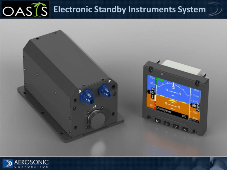
Electronic Standby Instruments System 1 OASIS: Introduction The OASIS is designed to serve as the secondary source of cockpit instrumentation and provides the following functions: • Attitude • Indicated Airspeed • Barometric Corrected Altitude • Slip/Skid • Heading (Optional, requires a magnetometer) 2 OASIS: LRU’s/Modular Design The OASIS modular designed allows installation flexibility by separating the display from the ASU enhancing installation flexibility in congested cockpits DU-1 (Display Unit) ASU MSU (Aerosonic Sensor Unit) (Magnetic Sensing Unit) Optional DU-2 (Display Unit) Optional 3 OASIS: Standard System and Options Standard system includes: • ASU, 1ea. • DU, 1ea. Enhanced system options: • Second DU • DU with NVS • ASU with internal standby battery • MSU for heading reference 4 OASIS: System Block Diagram GROUND POWER Aerosonic Sensor Unit ASU Power Magnetic Sensing Unit (Optional) Heading Data Attitude, Heading, Airspeed, Altitude Data Air Data AHRS Power Air Data AHRS Data Power AHRS PILOT CO-PILOT Display Unit DU-1 Display Unit DU-2 (Optional) 5 OASIS: Display Features Battery Status Slip-Turn Indicator Airspeed Tape Altimeter Tape Magnified Altitude Window Magnified Airspeed Window Heading Window (optional) Menu Select Keys Barometric Setting 6 OASIS: Part 27/29 Airspeed Window Red Min Airspeed Max Airspeed Color 0 VCAUTION Green VCAUTION VNE Power ON Yellow VNE Power ON Max Airspeed Value Red VNE Power OFF Red Cross-Hatched Line VNE power ON Yellow VCAUTION Green VNE Power OFF 7 OASIS: Display Unit The DU is installed on the instrument panel adjacent to the primary display or instruments and provides a secondary graphical display of all of critical, primary functions necessary for the continued safe flight and landing of an aircraft during a loss of primary instruments. The DU provides user interface for data entry and settings through a bezel keypad. The DU is directly connected to, and obtains power and sensor data from the remote mounted ASU. Features: • 4 inch diagonal screen • 3 inch ATI opening • Chassis depth: 1.35 inches • Bezel: 4 inches x 3 inches • Weight: .75 lbs • NVS compatible (Option) 8 OASIS: Display Unit 9 OASIS: Aerosonic Sensor Unit The ASU is a separate remote mounted LRU that provides power and sensor data to the DU. It’s connected to aircraft power and the pitot/static pneumatic lines. The ASU contains sensors required for the computation of Indicated Airspeed, Barometric Corrected Altitude, Attitude, Slip/Skid. Heading is available with the installation of an Aerosonic Remote Magnetometer. Power to the remote magnetometer is provided by the ASU. In addition the ASU has an optional internal battery that allows the OASIS to operate for a minimum of 1 hour without aircraft power. Features: • Dimensions: 3 x 3 x 6.25 inches • Weight: 2 lbs • Power: 28 Vdc nominal, 14 watts max (2 displays, 1 ASU) • Internal standby battery (Option) 10 OASIS: Aerosonic Sensor Unit 11 OASIS: Specification/Certification Operating Specification • Altitude: -1,500 to +55,000 ft. • Airspeed: 20 to 450 kts • Max roll/pitch rate: 200 deg/sec • Operating temperature • DU: -20º to +55º C • ASU: -40º to +70º C • Baro setting: 28.00 to 30.99 mb • Reliability: 10,000 hrs MTBF Certification • Software: DO178B level B • Environmental: DO 160F (Helicopter and Fixed Wing) • FAA /EASA TSO • TSO-C2d: • TSO-C4c: • TSO-C6e: • TSO-C10b: • TSO-C113: • TSO-C3e: • TSO-C46a • TSO-C179 Airspeed Instruments Bank and Pitch Instruments Direction Instrument, Magnetic Altimeter, Pressure Actuated, Sensitive Type Airborne Multipurpose Electronic Displays Turn and Slip Instruments Maximum Allowable Airspeed Indicators Rechargeable Lithium Cells and Lithium Batteries 12


