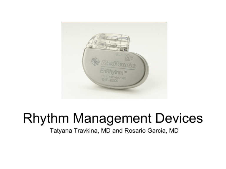
Rhythm Management Devices
Tatyana Travkina, MD and Rosario Garcia, MD
Overview
• Increased number of patients with implanted
cardiac devices
• Uncomfortable / lack of knowledge
• The always seems to be...
…To Magnet or Not to Magnet?
History: 1700’s
De facto cardiac electrostimulation began in the mideighteenth century with the use of currents from the Leyden
jar or Voltaic Pile (Allessandra Volta, 1799) to stimulate
cardiac nerves and muscles in animals and to attempt
resuscitation of intact dead animals.
Dr. William Hawes in London established The Humane
Society of London in 1774 AD - A fraternity devoted to
salvaging persons seemingly dead - motivated by similar
such society in Paris. Later on it became The Royal
Humane Society of London.
Squires, Henley and Fothergill suggested Electrostimulation
for resuscitation in a number of communications to the
Society between 1774 and 1748. Such an incidence is
described by Charles Kite in his “An Essay upon the
Recovery of the Apparently Dead.” (London, 1788) The 3year old child was taken up for dead after falling out of a
window. An “apothecary” was sent for, who could nothing;
then electrical resuscitation by an electrostatic generator
with a Leyden jar capacitor was used. (Fig.1)
History: 1800’s
•
In 1802, Nysten used a human cadaver shortly following
death by execution to demonstrate that the ability to
reactivate the heart electrically was lost earlier for the left
ventricle, later for the right ventricle, still later for the left
atrium and last for right atrium.
•
Later in the nineteenth century Althaus (1864) reported
successful resuscitation of cardiac arrest victims by
electrical currents applied through transthoracic needle.[
•
Dr.DeSanctis used “Re-animation Chair.”(Fig.2) as
described by Richmond Reece in his The Medical Guide
(1820). It had 3 pertinent features: a bellows to give forced
ventilation, a metallic tube to be inserted into the
esophagus and a voltaic pile attached at one pole to the
esophageal tube and at the other to an electrode. The
electrode was to be successively touched to “the regions of
the heart, the diaphragm and the stomach…” These
reports may have lead John Hunter to recommend in 1776
that electrostimulation be tried as the as the resort in the
resuscitation of drawing victims.
History: 1900’s
•
In 1899, Prevost and Battelli demonstrated that
electrical currents could cause ventricular fibrillation
that often could be reversed by another powerful
stimulus of either alternating or direct current.
•
Robinvitch in a series of reports from 1907 through
1909 confirmed this work and designed the first
portable electrical resuscitative apparatus for
ambulances.
•
MacWilliam, in many publications beginning in 1899
and extending to World War I, further elucidated the
pathophysiology of ventricular fibrillation and
described deterioration of cardiac pump function by
tachyarrhythmias as well as bradarrythmias.
History: 1930’s
•
In 1932, Albert Hyman developed a
machine for controlled repetitive
electrostimulation of heart and named
his device the “artificial cardiac
pacemaker.” [26] (Fig.3) In Hyman’s
Words:
•
“Finally on April 6,1930, I received
Grant No. 30-2 from the Witkin
Foundation to explore the possibility of
developing a practical machine, to be
used as an artificial pacemaker in
experimental animals.”
History: 1950’s
• In 1958, engineer Earl Bakken of
Minneapolis, Minnesota,
produced the first wearable
external pacemaker for a patient
of Dr. C. Walton Lillehei. This
transistorised pacemaker,
housed in a small plastic box,
had controls to permit
adjustment of pacing heart rate
and output voltage and was
connected to electrode leads
which passed through the skin of
the patient to terminate in
electrodes attached to the
surface of the myocardium of the
heart.
History: 1950’s
• The first clinical implantation into a
human of a fully implantable
pacemaker was in 1958 at the
Karolinska Institute in Solna, Sweden,
using a pacemaker designed by Rune
Elmqvist and surgeon Åke Senning.
• It connected to electrodes attached to
the myocardium of the heart by
thoracotomy. The device failed after
three hours. A second device was then
implanted which lasted for two days.
• The world's first implantable
pacemaker patient, Arne Larsson, went
on to receive 26 different pacemakers
during his lifetime. He died in 2001, at
the age of 86, outliving the inventor as
well as the surgeon.
Physiology
•
Delivery of electrical current (< 1.0 ms, <3.0 V) via an
insulated pacing lead to the heart muscle at a
preprogrammed rate.
•
The wires in a single-chamber pacemaker usually carry
pulses from the generator to the right ventricle
•
The wires in a dual-chamber pacemaker carry pulses
from the generator to the right atrium and the right
ventricle. The pulses help coordinate the timing of these
two chambers' contractions.
•
The wires in a biventricular pacemaker carry pulses
from the generator to the right atrium and both
ventricles. The pulses help coordinate electrical
signaling between the two ventricles. This type of
pacemaker also is called a cardiac resynchronization
therapy.
Indications for Permanent
Pacemaker Insertion- Bradycardia
Class I - There is evidence and/or general agreement that permanent pacing is indicated in patients
with sinus node dysfunction in the following settings:
• Documented symptomatic bradycardia, including frequent sinus pauses that produce symptoms.
(Level of Evidence: C)
• Symptomatic chronotropic incompetence. (Level of Evidence: C)
• Symptomatic sinus bradycardia that results from required drug therapy for medical conditions. (Level
of Evidence: C)
Class IIa - The weight of evidence or opinion is in favor of the usefulness of permanent pacing in
patients with sinus node dysfunction in the following settings:
• Heart rate <40 beats per minute when a clear association between significant symptoms consistent
with bradycardia and the actual presence of bradycardia has not been documented. (Level of
Evidence: C)
• Syncope of unexplained origin when clinically significant abnormalities of sinus node function are
discovered or provoked in electrophysiological studies. (Level of Evidence: C)
Class IIb - The evidence or opinion is less well established that permanent pacing in sinus node
dysfunction is beneficial in the following setting:
• Minimally symptomatic patients with chronic heart rate <40 beats per minute while awake. (Level of
Evidence: C)
Class III - There is evidence that permanent pacing in sinus node dysfunction is not useful and may be
harmful in the following settings:
• Asymptomatic patients. (Level of Evidence: C)
• Patients for whom the symptoms suggestive of bradycardia have been clearly documented to occur in
the absence of bradycardia. (Level of Evidence: C)
• Symptomatic bradycardia due to nonessential drug therapy. (Level of Evidence: C)
Indications for Permanent
Pacemaker Insertion- AV block
Indications for Permanent Pacemaker
Insertion- post-MI
Pacemaker mode codes
Table 1 The North American Pacing and Electrophysiology/British Pacing and
Electrophysiology Group (NASPE/BPEG) pacemaker codes:
Position I
Position II
Position III
Position IV
Position V
Pacing
chamber
Sensing
chamber
Response to
sensing
Programmabilit Antiy
tachycardia
functions
0=none
0=none
0=none
0=none
0=none
A=atrium
A=atrium
I=inhibited
R=rate
modulation
P=pace
V=ventricle
V=ventricle
T=triggered
S=shock
D=dual (atrium
and ventricle)
D=dual (atrium
and ventricle)
D=dual
(inhibited and
triggered)
) D=dual (pace
and shock)
Ventricular Pacing: Fixed-Rate and Demand Pacemakers
I.
The two modes of pacemaker function are fixed rate and demand.
I.
A fixed-rate pacemaker is one that fires at a specific preset rate, regardless of the patient's own
heart rate.
II. A demand pacemaker literally functions "on demand" (i.e., only when the patient's heart rate falls
below a preset value). A demand pacemaker has two distinct aspects:
I.
a sensing mechanism designed so that the pacemaker is inhibited when the patient's own heart
rate is adequate
II. a pacing mechanism designed to trigger the pacemaker when no intrinsic QRS complexes
occur within a predetermined period.
III. Demand units can be temporarily converted to fixed-rate mode by placing a special magnet on the
chest wall over the battery. The magnet test is routinely performed when the pacemaker rate is
being checked.
IV. Present-day demand-type pacemakers are also "programmable." This means that the pacing rate
can be adjusted once a pacemaker is implanted. Adjustment of rate is accomplished by placing a
special telemetry device on the chest wall to allow communication with the pacemaker.
V. Demand ventricular pacemakers usually are QRS (R wave) inhibited. They emit pulses only when
the spontaneous heart rate falls below the escape rate of the pacemaker (e.g., 70 beats/min) They
do not emit pulses when the patient's spontaneous heart rate is faster than the escape rate of the
pacemaker. Each time a QRS inhibited pacemaker senses a spontaneous QRS complex, formation
of a pacemaker pulse is inhibited.
Ventricular Pacing: Fixed-Rate and
Demand Pacemakers
I.
The QRS-inhibited pacemaker also has a refractory period (e.g., 0.4 second) that begins
whenever the pacemaker senses a QRS complex or emits a pulse.
I.
During the refractory period the pacemaker cannot sense another R wave. However, if
spontaneous ventricular beats or ventricular premature complexes occur during the refractory
period, they are not inhibited but appear on the ECG.
II. The refractory period is followed by an alert period, during which the pacemaker can sense an R
wave. If no QRS complex is sensed by the end of the alert period, the pacemaker emits another
pulse.
I. However, if a spontaneous QRS complex occurs, the pacemaker is recycled into another
refractory period and then into another alert period.
Dual-Chamber Pacing
I. In dual-chamber pacemakers, electrodes are inserted into both the right atrium and right ventricle.
II. The atrial lead is able to sense the patient's intrinsic P waves and stimulates the atrium when the
atrial rate becomes too slow.
I. The circuitry is designed to allow for a physiologic delay between atrial and ventricular
stimulation. This atrioventricular (AV) delay is analogous to the PR interval seen in normal
conduction.
III. Dual-chamber pacing is helpful in maintaining physiologic timing between atrial and ventricular
systole.
I. When ventricular pacing alone is used, this physiologic timing is lost. In some patients the loss
of timed atrial contractions causes a marked reduction in cardiac output.
II. Dual-chamber pacing produces a significant improvement in the cardiac performance of these
individuals. In selected patients, dual-chamber pacing may allow a physiologic increase in
ventricular rate during exercise.
Pacemaker mode codes-Example
•
•
•
•
•
You have a patient in 3rd degree heart block with
a pacemaker in DDD mode. What does that
mean?
The first D in DDD is the area PACED. The D
stands for DUAL, so this pacemaker, paces
both the atrium and the ventricle.
The second letter stands for Area SENSED, so
this pacemaker senses both the atrium and the
ventricle.
The third letter stands for what it does, and the
D stands for Dual inhibited.
This pacemaker can be INHIBITED by:
•
Electrical Noise Caused by Electro cautery
•
Refractory Period electrical activity from an
atrial contraction and it will not pace the
atrium.
•
electrical activity of a ventricular contraction,
and not pace the ventricle, or both.
Rate-adaptive/rate-modulated
pacing
I.
normal heart rate response to increased
physiological demand is linearly related to oxygen
demand/consumption
II. greater proportion of rate-adaptive sensors belong
to a secondary class of sensors that detect
physiological changes as a consequence of
exercise such as:
I. such as QT interval shortening
II. increase in respiratory or minute-ventilation rate
III. increased mean atrial rate
IV. rise in central venous temperature
V. decrease in venous blood pH
VI. increase in right ventricular stroke volume
VII. increase in ventricular inotropy (e.g. peak
endocardial acceleration and ventricular
impedence variation).
Questions
1.Which of the following is the major indication for a permanent pacemaker?
a.History of multiple prior myocardial infarctions
b.Symptomatic bradyarrhythmia
c.Digitalis toxicity
d.Ventricular bigeminy
e.Paroxysmal supraventricular tachycardia
2.What does the following rhythm strip show?
a.Failure to sense
b.Failure to pace
c.Normal pacemaker function with a ventricular premature beat
d.Failure to sense and pace
3.What is shown in the following rhythm strip?
Practical Pacemaker Codes
Code
What is it
Who gets it
AOO
Atrial pace, no sense, no
inhibitions
Sick sinus syndrome with intact
conduction in the operating room
with bovie. eg. Cardiac case, in
OR, with bovie, with heart rate low
from narcotics.
AAI
Atrial pace, atrial sense,
inhibited by atrium
Sick sinus syndrome with intact
conduction system.
VOO
Ventricular pace, no sense, no
inhibit
Third degree heart block in OR
with atrial fibrillation. Why atrial
fibrillation? Because you cant
effectively pace the atrium if it is
fibrillating.
VVI
Ventricular pace, ventricular
sense, ventricular inhibit
Third degree heart block with atrial
fibrillation.
DOO
Dual pace, no sense, no
inhibitions
Third degree heart block in OR
with bovie.
DVI
Dual pace, ventricular sense,
ventricular inhibit
Third degree heart block with
supraventricular tachycardias
DDD
Dual pace, dual sense, dual
inhibit
Third degree heart block.
ICD codes
I.
ICDs have 4 main functions.
I. They sense atrial or
ventricular electrical activity,
II. classify these signals to
various programmed “heart
rate zones,”
III. deliver tiered therapies to
terminate ventricular
tachycardia or fibrillation,
IV. pace for bradycardia.
II. The most important aspect of
ICD management preoperatively
is deactivating the tachycardia
response of the device to avoid
inappropriate pacing or shocks
due to electromagnetic
interference.
Position
I
Position
II
Position
III
Position
IV
(or use
pacemaker
code)
Shock
Chamber
Antitachycar Tachycardia
dia Pacing
Detection
Chambers
Antibradyca
rdia Pacing
Chambers
O=none O=none E=Electri O=none
cal
A=Atrial A=Atrial H=Hemo A=Atrial
dyn.
V=Ventri V=Ventri
cle
cle
D=Dual D=Dual
V=Ventri
cle
D=Dual
Why do we care?
1) Will it quit during surgery?
2) Will the patient die if it quits?
3) Will the pacemaker cause a dysrhythmia?
4) Will the patient get shocked if he / she has
an ICD?
5) Will the ICD cause a dysrhythmia?
What we need to know
A.
B.
C.
D.
E.
F.
What is the device?
What brand and model?
Who controls it?
Does your hospital have a programmer for this make and model?
What is the magnet mode?
Why does the patient have a pacemaker? This is important because if
the patient has it for third degree block, you should treat the device as
if the his life depends on it.
G. What rhythm does the patient have when the pacemaker is shut off? If
the rhythm is asystole, treat the device with a certain respect and
caution.
Clinical Vignette #1:
A 56-year-old male is admitted after a motor vehicle
accident. He was intubated in the field, and is coming
directly to the operating room for free air in the abdomen.
A chest x-ray taken in the emergency department shows
the following:
A chest x-ray can be extremely informative for patients
coming for emergency surgery. A chest x-ray can identify
the device type, leads, and manufacturer.
From this x-ray, it is clear that the patient has 3 leads: a
right atrial lead, a right ventricular lead, and a coronary
sinus lead. In addition, the right ventricular lead is a
shocking coil, which is identified by the thicker, denser
distal portion of the lead.
From this chest x-ray, it is clear that the patient has an
ICD due to the shocking coil, and the coronary sinus lead
suggests resychronization therapy for low ejection
fraction. From this x-ray, this patient should be treated like
any patient with cardiomyopathy.
What we need to know
A. What is the device:
What we need to know
B. What is the model
Patients carry a card you can get an X-ray of the device and
see the make on the circuit board. Moreover,
you can see the leads and tell what the device is.
The easiest way to find out what the device is, is to call
Medtronic Bradyarrhythmia Products at 800-505-4636. The
phone number is on the web at http://www.medtronic.com.
They are open 24/7/365. If you call and identify the patient,
they will tell you if the patient has a Medtronic device, or give
you a number for the other manufacturers such as Guidant,
etc.
What we need to know
What is the magnet mode:
The magnet is NOT MAGICAL. The magnet
simply throws a programmable switch in
the pacemaker. It changes it from one mode
to another. The magnet mode depends on
the
brand of pacemaker, the type of device,
whether magnet mode is turned on, and it
may
even depend on the level of battery charge
in the device. In some implantable devices
the
magnet mode may shut off the device. In
others it may make the device listen for
information from a radio frequency controller.
It may change modes to another type of
function. The magnet throws a
programmable switch. It may or may not be
What we need to know
What is the magnet mode cont.
I.
II.
I.
II.
III.
IV.
III.
Activates magnetic reed switch
Model dependent behavior with
magnet
Asynchronous pacing – most
common
No apparent rate or rhythm
change
Brief asynchronous pacing and
then return to programmed value
Continuous or transient loss of
pacing
Magnets will cause most DDDs to
convert to DOO at about 85 with a
BOL (beginning of life) battery, and to
VOO at a rate of about 65 at ERI
(effective replacement interval) is
reached to conserve power.
What we need to know
Magnet problems
I.
Many ICDs have built-in VOO pacemakers. If the
patient has no pacemaker implanted, the built-in
ICD pacemaker will become active in the event that
a shock is delivered and the patient goes into
asystole. Rate is usually minimal, at about 40 or so.
II. If the patient’s underlying rhythm is very close to
the pacemaker’s setting.
I. If you reprogram the pacemaker to an DOO or
VOO mode, you might cause a pacemaker
stimulus at the wrong point on the patient’s
cycle and induce VT or VF.
III.
If there is an ICD. All ICDs are inhibited by the
magnet but no pacemakers with ICDs are affected
by the magnet.
I.
In general, magnets will not affect ICD antibradycardia pacing
mode or rate (except ELA and Guardian 4202/4203)
Intermedics devices transiently change the pacing rate (VVI
mode) to reflect battery voltage. Interrogating the device and
calling the manufacturer remain the most reliable method
for determining magnet response.
Magnet
Mode
Explanation
Designation
Pacemaker
Company
AUTO
Biotronik (except
INOS and DROMOS) ASYNCH
SYNCH
Boston
Scientific/Guidant
Medical/CPI
ASYNCH
OFF
EGM mode
No change, magnet is ignored. OFF is the magnet mode after a “power on reset,” which can occur secondary to EMI
No change in pacing. Magnet application initiates data collection
Asynchronous pacing at 85 beats/min if okay, SSI at 65 beats/min regardless of original programming if ERI detected
(single-step change). Most Medtronic pacemakers emit one or more ventricular pulses during the first 3-7 asynchronous
events (which might be at a rate of 100 beats/min) at a reduced pulse width or voltage to demonstrate the adequacy of
ventricular pacing output. Also, Medtronic pacemakers default to SSI pacing at 65 beats/min, without rate
responsiveness, on detection of ERI, regardless of whether a magnet is present
Medtronic
St. Jude
Medical (not
including
Telectronics)
If battery okay, 10 asynchronous events at 90 beats/min, then returns to original programmed mode, without rate
responsiveness. Pacing is at the lowest available rate (LRL, sleep rate, or hysteresis rate). If battery at ERI, 10
asynchronous events at 80 beats/min in the VOO mode, then either VDD (dual-chamber) or VVI (single-chamber)
pacing at 11% lower than the lowest available rate. For any dual-chamber mode (DDD, DDI, or VDD), the AV delay
shortens to 100 msec while the magnet is in place
Asynchronous pacing at 90 beats/min if battery okay. At ERI, 80 beats/min (single-step change) in the VOO mode
regardless of original programming. For any dual-chamber mode (DDD, DDI, or VDD), the AV delay shortens to
100 msec while the magnet is in place
If battery okay, pacing in original programmed mode, without rate responsiveness. Pacing is at the lowest available rate
(LRL, sleep rate, or hysteresis rate). If battery at ERI, either VDD (dual-chamber) or VVI (single-chamber) pacing at 11%
lower than the lowest available rate. For any dual-chamber mode (DDD, DDI, or VDD), the AV delay shortens to
100 msec while the magnet is in place
Asynchronous pacing at 100 beats/min if okay, 85 beats/min at ERI (single-step change). The Insignia model has an
intermediate step at 90 beats/min at IFI. For Triumph and Prelude models, see Medtronic pacemakers, below
Battery Test
OFF
“SJM” Event
x-ray snapshots
logo Event
snapshots +
Battery Test
Battery Test
Paces
OFF
etter
x-ray
VARIO mode
logo
(present in
(ψ)
some models)
Asynchronous pacing at 98.6 beats/min gradually decreasing to <86.3 beats/min at ERI
No magnet response
No change in pacing. Magnet application causes pacemaker to collect data. Identity and Entity models lack this feature
For a magnet placed 2 seconds, pacing mode and rate are unchanged and the device stores an EGM. If the magnet is
placed ≥5 seconds, the Battery Test mode (see above) is activated. Identity and Entity models lack this feature
Asynchronous pacing, with rate depending on the specific model. In general, a pacing rate of less than 90 beats/min
should prompt further evaluation
No magnet response
VARIO results in a series of 32 asynchronous pacing events. The rate of the first 16 paces reflects battery voltage, which
gradually declines from 100 to 85 beats/min at ERI. The next 15 paces are used to document the ventricular pacing
capture safety margin. The rate will be 119 beats/min with gradually declining pacing voltage. The 16th pace of this
group is at no output. The next pace restarts the 32-event sequence. The 32-event sequence repeats as long as the
magnet remains in place
Device and Electromagnetic Interference
I. The most common issue arising in the perioperative
I. Any apparatus that emits radiofrequency waves between 0 and 10 9 Hz
can generate EMI and therefore interfere with proper device function.
II. Higher frequency waves (e.g. X-rays, γ-rays, infrared, and ultraviolet light)
are unlikely to cause interference with CIED function, though repeated
and/or prolonged exposure to certain types of radiation can cause
deterioration of insulation within the device with resultant short-circuiting
or other electrical problems.
II. For pacemakers in general, inhibition of pacing due to oversensing is the most
common result of exposure to EMI, though in some cases, sudden
asynchronous pacing, reversion to a programmed backup mode (often VVI or
VOO mode), or both can be seen.
III. With an ICD, EMI can result in inappropriate delivery of a defibrillatory shock.
IV. Thus, if pacing modes appear to be changing abruptly or intermittently on
ECG monitors, unrecognized EMI should be considered.
V. The vast majority of devices now use bipolar leads; however, unipolar leads
are still sometimes used when epicardial leads are placed (often in the
paediatric population) and in adults with older devices.
I. Bipolar leads minimize the physical distance over which the circuit is
completed because both the anode and cathode are located very close to
each other on the lead itself. (6 inch rule)
II. In contrast, with unipolar leads, the lead tip acts as the cathode and the
pulse generator acts as the anode to complete the circuit.
Electrocautery
(monopolar>>>>bipolar)
Evoked potential monitors
Nerve stimulators (twitch
monitors)
Fasciculations
Shivering
Large tidal volumes
External defibrillation
Magnetic resonance imaging
Radio frequency ablation or
lesioning
Extracorporeal shock wave
lithotripsy
Electroconvulsive therapy
What we need to know
When to reprogram?
I. Any rate-modulated pacing device
II. Special pacing indication (hypertrophic obstructive cardiomyopathy, dilated
cardiomyopathy, pediatric patients)
III. Pacemaker-dependent patients (3rd degree heart block)
IV. Major procedure in the chest or abdomen
V.
Rate enhancements present that should be disabled
VI. Lithotripsy
VII. Transurethral resection (electrolytes)
VIII. Hysteroscopy (electrolytes)
IX. Electroconvulsive therapy
X.
Succinylcholine use (K change)
XI. Magnetic resonance imaging (generally contraindicated by device
manufacturers but, as of 2009 MRI safe devices available)
Reprogramming a PM to asynchronous pacing at a rate more rapid than
the patient's underlying rate usually ensures that no oversensing during
electrocaudery will take place, thus protecting the patient.
Suggested algorithm for preoperative decision-making regarding a modern CIED with bipolar
leads.
Stone M E et al. Br. J. Anaesth. 2011;107:i16-i26
© The Author [2011]. Published by Oxford University Press on behalf of the British Journal of
Anaesthesia. All rights reserved. For Permissions, please email:
journals.permissions@oup.com
ICD/Pacemaker failure
I. Device failure is a rare perioperative occurrence that can result
from a failure of the device to sense, a failure to pace, or damage
to the generator.
II. Most perioperative events that are thought to be pacemaker
failures are really rate adaptive features that have not been
disabled.
I. For example, current pacemakers have minute ventilation
sensors that increase the pacing rate for patients during
exercise. EMI can change body impedance which might cause
the pacemaker to pace at a fast rate since the pacemaker
“sees” the EMI as increased physiologic demand.
III. Electrical reset is also a very rare occurrence that can happen
when electrocaudery directly contacts the cardiac device generator
and results in device failure.
I. Therapeutic radiation is the usual perioperative culprit, and it is
rare in the setting of monopolar cautery or cardioversion.
II. If electrical reset does occur, each CIED, depending on
manufacturer and device, will default to a particular setting.
While the default setting may not be optimal for one’s specific
patient, it will function safely until the device can be interrogated
to determine if it can be reprogrammed or replaced.
III. Damage to the generator may also be caused by
electrocautery applied to the generator; therefore, the path of
EMI should be directed away from the generator to prevent
current flow across the device.
IV. Device leads may be damaged intraoperatively, leading to failures
in sensing and/or pacing. Electrocaudery may produce enough
current to flow from the generator to the pacing electrode and could
possibly damage the tissue-lead interface. This acute injury may
lead to loss of pacing and sensing.
ICD/Pacemaker failure
Undersensing: An intrinsic depolarization occurs in the atrium,
but this depolarization is not sensed by the pacemaker.
I.
Improper lead position: Lead has to be positioned at an ideal location for optimal
function, otherwise it can cause undersensing.
II. Improper programming: Programming the lead sensitivity too high may cause
undersensing.
III.
Lead maturation or dislodgement (as shown):
I.
Lead maturation or dislodgement cause sensing and capture malfunction due to poor signal strength.
II. Atrial lead dislodgement. Loose connection at connector due to inadequate contact of the pin and
connector there is intermittent undersensing and loss of capture
III. Artifact due to monitor malfunction or loose limb lead connection.
I.
An abrupt loss of a portion of the QRS complex followed by a flat line can be observed. If R-R
intervals are matched, 2 QRS complexes are missing during the pause. If it is due to a dislodged
lead, a pacing artifact with no capture should be observed.
ICD/Pacemaker
Failure
Causes cont:
• Incompatible connector: Incompatible connector causes sensing and
pacing malfunction.
• Battery depletion: This can cause undersensing, loss of capture, or
loss of output.
• Magnet application: Magnet inhibits sensing of cardiac or non-cardiac
electrical events by the pacemaker and it reverts to fixed-rate pacing
function (DOO or VOO). Pacemaker reverts back to the programmed routine
upon removal of the magnet.
ICD/Pacemaker failure
Undersensing causes cont.
I.
Electromagnetic interference (EMI):
I. DC shock cause reversion to back-up mode, transient increases in capture threshold and loss of
capture, and damage to the pulse generator and circuitry.
II. Electrocautery can inhibit the pacing stimuli or trigger ventricular pacing due to atrial oversensing.
II. Air pocket in unipolar pacers:
I. In unipolar pacers, lead has a single stimulating electrode, the cathode, with the anode connected
to an indifferent electrode, usually the outer surface of the pulse generator that has to be in
constant contact with the subcutaneous tissue of the person.
II. In dry pocket situations there is inadequate contact between pulse generator and tissue causing
inappropriate sensing and pacing.
III. Post defibrillation or cardioversion: DC shock causes pacemaker reversion to back-up mode,
transient increases in capture threshold and loss of capture, and damage to the pulse generator and
circuitry.
IV. Electrolyte abnormality such as hyperkalemia or acidosis: Hyperkalemia causes both sensing
and pacing malfunction due to a reduction of the electronegativity of the resting myocardial potential.
I. Potassium, calcium, and magnesium abnormalities can raise depolarization thresholds.
II. Potassium flux, ionized calcium levels, and acid-base equilibrium can be affected by
hyperventilation and hypoventilation.
ICD/Pacemaker failure
Failure to capture
•Dry (air) pocket in unipolar pacer
•Circuit failure
•Impending battery depletion
•Inadequate programmed output with higher threshold
•Insulation break
•Partial conductor coil fracture
•Lead maturation, dislodgement, or perforation
•Poor or incompatible connection at connector block
•Conditions that increase the capture threshold, such as
metabolic and electrolyte abnormalities (Potassium),
medications, and myocardial infarction
ICD/Pacemaker failure
Factors increasing pacemaker threshold
I.
Myocardial ischemia or
infarct
II. Electrolyte disturbance
I. Potassium
II. Calcium
III. Acidosis or alkalosis
IV. Hypoxia or hypercapnia
V. Abnormal antiarrhythmic
drug level especially
Class I and beta blockers
ICD/Pacemaker failure
Electroconvulsive therapy (ECT)
I.
II.
ECT is relatively safe for patients with pacemakers, because of the
localized application of the electrical stimulus to the head, hence a low
probability for the occurrence of problems.
Sometimes the seizure may generate myopotentials which may inhibit the
pacemaker, and transient electrocardiographic changes (e.g., increased Pwave amplitude, altered QRS shape, T-wave and ST-T abnormalities) may
occur and additional cardiac complications (e.g., arrhythmia or ischemia)
may occur in patients with pre-existing cardiac disease.
TENS
I.
II.
III.
Electrical stimulating techniques such as transcutaneous electrical nerve
stimulation (TENS) consists of several electrodes placed on the skin and
connected to a pulse generator that applies 20 μs rectangular pulses of 1–
200 V and 0–60 mA at a frequency of 20–110 Hz.
This repeated frequency is similar to the normal range of heart rates, so it
can create a far field potential that may inhibit a cardiac pacemaker.
TENS can be used safely in patients with pacemakers and defibrillators
with close monitoring and use in close proximity to the device is not
advised
ICD/Pacemaker failure
Radiofrequency ablation (RFA)
I.
The radiofrequency current path should be kept as far away from the pulse
generator and lead system as possible and to avoid direct contact between
the ablation catheter and the device
Radiation therapy
I.
II.
III.
IV.
V.
The high-energy ionizing radiation used in radiation therapy can cause
significant damage to the semiconductors of pacemakers, even at very
small doses.
Generally, doses in excess of 5000 rads are required to cause pacemaker
malfunction but as little as 1000 rads may induce pacemaker failure or
cause runaway pacemaker.
Pulse generator recovery may occur long after the end of the radiation
treatment, but it is mostly incomplete, and the pacemaker cannot be used
reliably thereafter.
Thus, in pulse generators exposed to radiation, transient loss of function
should be regarded as a precursor of permanent damage. Hence it is
essential to follow guidelines for ensuring the lowest possible radiation
dose to the pacemaker and careful follow-up should be performed during
and after completion of the radiation therapy. The device must be outside
the field of radiation.
The low-energy X-rays used for diagnostic radiology have not been
reported to have any adverse effect in pacemakers.
Pacemaker
failure
BP stable
Observe
O2
Atropine
Hypotension
Epinephrine
Isoprotenerol
Asystole
Temporary
pacing
CPR
Summary
Pacemaker and AICD implanted patients undergoing
emergency surgery:
1. Try get information regarding pacemaker or AICD at
earliest possible or if time permits
2. Contact pacemaker or AICD clinic or manufacturer
3. Reprogram the device function in selective group of
patients
4. If possible avoid electrocautery use within 6 inches
of the device
1. If necessary consider use of bipolar or harmonic
scalpel
2. Be ready for alternate mode of pacemaker and
defibrillator if necessity arises
References
1.
2.
3.
4.
5.
6.
M. E. Stone, B. Salter,and A. Fischer Perioperative management of patients with cardiac
implantable electronic devices Br. J. Anaesth. (2011) 107
Miller: Miller's Anesthesia, 7th ed. Chapt 43.
Apfelbaum JL, Belott P, Connis RT, et al.; for the American Society of Anesthesiologists
Committee on Standards and Practice Parameters. Practice advisory for the perioperative
management of patients with cardiac implantable electronic devices: pacemakers and
implantable cardioverter-defibrillators. Anesthesiology 2011;114:247-61.
American Society of Anaesthesiologists Task Force on Perioperative Management of
Patients with Cardiac Rhythm Management Devices. Practice advisory for the perioperative
management of patients with cardiac rhythm management devices: pacemakers and
implantable cardioverter-defibrillators: a report by the American Society of
Anaesthesiologists Task Force on Perioperative Management of Patients with Cardiac
Rhythm Management Devices. Anesthesiol 2005;103:186-98.
Managing Cardiovascular Implantable Electronic Devices (CIEDs) During Perioperative Care
Jacques P. Neelankavil, MD; Annemarie Thompson, MD; Aman Mahajan, MD, PhD. APSF
Newsletter, Fall 2013.
M.L. Dohrmann, N.F. GoldschlagerMyocardial stimulation threshold in patients with cardiac
pacemakers: effect of physiologic variables, pharmacologic agents, and lead electrodes
Cardiol Clin, 3 (1985), pp. 527–537


