Function Block Programming: An Overview
advertisement
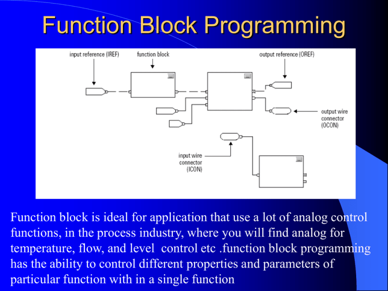
Function Block Programming Function block is ideal for application that use a lot of analog control functions, in the process industry, where you will find analog for temperature, flow, and level control etc .function block programming has the ability to control different properties and parameters of particular function with in a single function Function Block Elements INPUT REFERENCE (IREF): supply a value from an input device or tag OUTPUT REFERENCE (OREF): send a value to an output device or tag FUNCTION BLOCK: perform an operation on an input value or values and produce an output value or values OUTPUT WIRE CONNECTOR (OCON) / INPUT WIRE CONNECTOR (ICON): transfer data between function blocks when they are:1. far apart on the same sheet 2. on different sheets within the same routine 3. disperse data to several points in the routine Latching data / Order of Execution Latching Data: data in that IREF is latched for the scan of the function block routine. controller updates all IREF data at the beginning of each scan. Order of Execution: is determined when verified or download to controller With sequentially blocks, the execution order moves from input to output indicator. Execution order is only relative to the blocks that are wired together. To identify which block to execute first, mark the input wire that creates the loop (the feedback wire) with the Assume Data Available D2SD Example Example The D2SD instruction is typically used to control on-off or open-close devices such as pumps or solenoid valves. In this example, the D2SD instruction controls a solenoid valve adding corn syrup to a batch tank. As long as the D2SD instruction is in Program control, the valve opens when the AddSyrup input is set. The operator can also take Operator control of the valve to open or close it if necessary The solenoid valve in this example has limit switches that indicate when the valve is fully closed or opened. These switches are wired into the FB0 and FB1 feedback inputs. This allows the D2SD instruction to generate a FaultAlarm if the solenoid valve does not reach the commanded state within the configured Fault Time. Select (SEL) The SEL instruction uses a digital input to select one of two inputs The SEL instruction selects In1 or In2 based on SelectorIn. If SelectorIn is set, the instruction sets Out = In2. If SelectorIn is cleared, the instruction sets Out = In1. Out becomes an input parameter for function_block_C. Selected Summer (SSUM) The SSUM instruction uses Boolean inputs to select real inputs to be algebraically summed The values of select1 and select 2 determine whether to select analogInput1 and analog_input2, respectively. The instruction then adds the selected inputs and places the result in Out. Out becomes an input parameter forfunction_block_C. Function Block (FB) Function Blocks are the basic elements of a control system. Function Blocks consist of two parts; a set of input and output parameters and an algorithm specific to the specific type of function block. Function Block language is designed to control “parameter areas”. Function Block is natively suited for continuous processes with analog values such as PID Loops Function Block Diagram (FBD) Language • Graphical Free-form drawing / programming environment – Place instructions blocks and draw connections to pass parameters – Position and organize blocks based on application to improve readability – Floating text boxes provide application documentation (Planned for V12) • Automatic sheet execution order determined by block interconnections – Eliminates program creation process – Simplifies program modification • Comprehensive FBD functions are native inside the Logix5000 – Common LD blocks in FBD – 42 new process and drive control functions • ActiveX faceplates for key FBD blocks streamline HMI development Applications for Function Block Diagram • Ideal for analog loop control algorithms – – – – Graphically represents control loops Highly visual language is easy to understand Resembles circuit diagrams Commonly used in Distributed Process Systems (DCS) • Continuous or Batch Process control loops • Drive control loops – Speed, position, and tension regulation… – Rewind, winder, and dance control… – Provide a foundation for applications that previously used the Reliance Automax Process Control – Found in many manufacturing, motion and packaging applications. Robotic assembly, such as that found in automotive production, can be characterized as discrete process control. Most discrete manufacturing involves the production of discrete pieces of product, such as metal stamping. Batch – Some applications require that specific quantities of raw materials be combined in specific ways for particular durations to produce an intermediate or end result. One example is the production of adhesives and glues, which normally require the mixing of raw materials in a heated vessel for a period of time to form a quantity of end product. Other important examples are the production of food, beverages and medicine. Batch processes are generally used to produce a relatively low to intermediate quantity of product per year (a few pounds to millions of pounds). Continuous – Often, a physical system is represented though variables that are smooth and uninterrupted in time. The control of the water temperature in a heating jacket, for example, is an example of continuous process control. Some important continuous processes are the production of fuels, chemicals and plastics. Continuous processes, in manufacturing, are used to produce very large quantities of product per year(millions to billions of pounds). Discrete Control out put discreet/ analog with a number of input /output parameter Feedback Input based on response time Input upper and lower range Auto manual modes Outputs range upper lower Gain

