Guidelines for Drawing Freebody Diagrams
advertisement
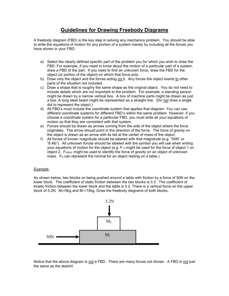
Guidelines for Drawing Freebody Diagrams A freebody diagram (FBD) is the key step in solving any mechanics problem. You should be able to write the equations of motion for any portion of a system merely by including all the forces you have shown in your FBD. a) Select the clearly defined specific part of the problem you for which you wish to draw the FBD. For example, if you need to know about the motion of a particular part of a system, draw a FBD of the part. If you need to find an unknown force, draw the FBD for the object (or portion of the object) on which that force acts. b) Draw only the object and the forces acting on it. Any forces the object exerts to other parts of the situation not included. c) Draw a shape that is roughly the same shape as the original object. You do not need to include details which are not important to the problem. For example, a standing person might be drawn by a narrow vertical box. A box of machine parts might be drawn as just a box. A long steel beam might be represented as a straight line. (Do not draw a single dot to represent the object.) d) All FBD’s must include the coordinate system that applies that diagram. You can use different coordinate systems for different FBD’s within the same problem. However, if you choose a coordinate system for a particular FBD, you must write all your equations of motion so that they are consistent with that system. e) Forces should be drawn as arrows coming from the side of the object where the force originates. The arrow should point in the direction of the force. The force of gravity on the object is drawn as an arrow with its tail at the center of mass of the object. f) All forces of known magnitude should be labeled with that magnitude (e.g. “50N” or “8.4lb”). All unknown forces should be labeled with the symbol you will use when writing your equations of motion for the object (e.g. F12 might be used for the force of object 1 on object 2. FGRAV might be used to identify the force of gravity on an object of unknown mass. FN can represent the normal for an object resting on a table.) Example: As shown below, two blocks on being pushed around a table with friction by a force of 50N on the lower block. The coefficient of static friction between the two blocks is 0.3. The coefficient of kinetic friction between the lower block and the table is 0.2. There is a vertical force on the upper block of 5.2N. M2=5kg and M1=15kg. Draw the freebody diagrams of both blocks. 5.2N M2 50N M1 Notice that the above diagram is not a FBD. There are many forces not shown. A FBD is not just the same as the sketch! Solution: y y F21 5.2N x x FFRIC-21 M2 50N M1 FFRIC-12 FFRIC-T1 FGRAV-2 F12 FGRAV-1 FT Notes: F12 is the normal force of block 1 on block 2. F21 is the normal force of block 2 on block 1. They form an action-reaction force pair. They are equal in magnitude, opposite in direction. FFRIC-12 is the frictional force of block 1 on block 2. FFRIC-21 is the frictional force of block 2 on block 1. They also form an action-reaction force pair. FT is the force of the table on block 1. Since it is a “normal force”, we could have labeled it FN, but notice that F21 is also a normal force. So there is no single “normal force” in this case. If we label every normal force in the problem as FN, there will be confusion. Also note that since we are not drawing the FBD of the table, we don’t see the third law force pair partner for FT. Notice each FBD includes an indication of the coordinate system to be used in writing the equations for that diagram. The coordinate systems don’t have to be the same for all FBD’s within a problem as long as you include the relationship between them when solving your problem. The equations of motion you might write from the FBD of block 2 are: Fy = may -5.2N – FGRAV-2 + F12 = m2ay Fx = max FFRIC-12 = m2ax The mass represented by the m on the right-hand side of both these equations is the mass of the object you drew the freebody diagram of. In this case that is block 2 (15kg). This freebody diagram might be used in a situation where the system started from rest and you were asked to find the magnitude of all of the forces on block 2. You could continue this problem by asking “What is the maximum force that could replace the 50N and still have the top block not slide off?”
