3) Final Proposal Presentaion
advertisement
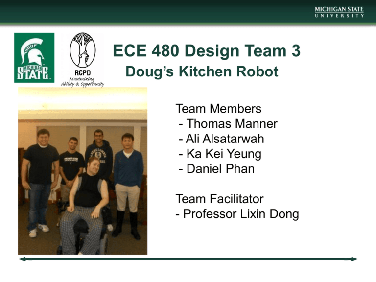
ECE 480 Design Team 3 Doug’s Kitchen Robot Team Members - Thomas Manner - Ali Alsatarwah - Ka Kei Yeung - Daniel Phan Team Facilitator - Professor Lixin Dong Introduction • Project Objectives: - Design and construct a robotic arm capable of handling heavy lifting, stirring, and other kitchen activities. - Design a controller interface that is easily operated and accommodated for people with limited muscular movements. - The goal of our design project is to assist Doug in lifting and moving items within the confines of his countertop, stove, and sink. Meal Buddy unit Background: -Most of these commercial products in market , especially the automatic modules are capable of lifting only light objects. -Most of these commercial products e very automatic and precision based. - According to pilot study conducted by the University of Central Florida found that most users Including quadriplegic’s preferred manual controls and considered the automated designs “too easy and too automated.”[1]. Customer Needs/Requirements • Capabilities of the Robotic arm - Lift and carry a pot of water weighing 40lbs - Variable Speed movements, but limited to a safe range - Gripper and hooks for picking up kitchenware - Rotating gripper to assist in stirring food on the stove - Sensors for when Robotic arm reaches end of the track • Controller Interface - Three joystick design - Wireless communication - Tall joystick for operation ease - Programmed for Cartesian movement of Robotic arm Customer Needs/Requirements (cont’d) • Miscellaneous Needs - Designed for robustness and durability - Easy to maintain - Designed with easily replaceable circuitry and mechanical components. - The controls should be programmable for future feature additions Robotic Arm Designs Figure 1: Concept I Wall Mounted Cartesian Robotic Arm Figure 2: Concept II Triple Joint Robotic Arm Robotic Arm Designs (cont’d) Figure 3: Concept III Wall Mounted Cartesian Robotic Arm (2 Axes) with Rotating Arm Proposed Design Solution • The project must meet requirements for basic function set by the sponsor, without sacrificing safety. For the robotic arm, Figure 3 Concept III was chosen since 3 of the 4 motors are mounted near the wall. This will reduce the amount of torque on the overall system. Concerns involving the payload the gripper can hold was solved by adding hooks for heavier load applications. Risk Analysis • Power Management- Motors of the robotic arm will draw a relatively high amount of current. Safe wiring and encasement of the circuits will minimize the safety risk involved. • Operating Speed- Speed will need to be kept within a safe speed range whether carrying a load or not. • Gripper type- The gripper will need to work in conditions regularly encountered in the kitchen. The gripper will have to be waterproof. • Torque- The amount of weight of the robotic arm would put stress on certain parts of the robot. By choosing a design with most of the motors mounted near the wall, the amount of torque will be minimized. • Testing- One of the challenges in this project is the high cost of the mechanical materials used to build the robotic arm. Since building a prototype is not an option, testing at each stage of construction is critical.
