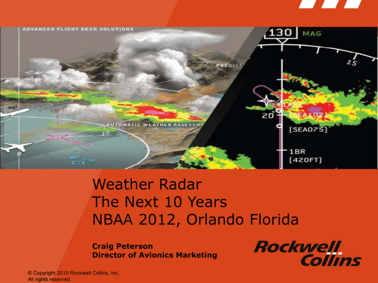
Weather Radar
The Next 10 Years
NBAA 2012, Orlando Florida
Craig Peterson
Director of Avionics Marketing
© Copyright 2010 Rockwell Collins, Inc.
All rights reserved.
Rockwell Collins Radar (Historical Perspective)
1956
First Rockwell Collins Airborne Weather Radar
1980
First Rockwell Collins Solid State Weather Radar (Air Transport)
1987
First Rockwell Collins Solid State Weather Radar (Corporate and Gen Av)
1995
Predictive Windshear Systems Certified (Air Transport)
2002
Multiscan Radar Certifies (Auto-tilt, Auto Ground Clutter Suppression, Global Geographic
Correlation)
2009
Multiscan Radar Certifies (Corporate and Regional Jet Platforms)
2013
Multiscan “Version 2” Enters the Air Transport Market Segment
2013
Predictive Windshear Enters Corporate and Regional Market Segment
50+ Years and 40K Units of Airborne Radar at Rockwell Collins
The contents of this document are proprietary to Rockwell Collins, Inc.
2
What Is MultiScan?
The contents of this document are proprietary to Rockwell Collins, Inc.
3
MultiScan Baseline Functionality
300 NM
Attenuation Alert
• Accurate Weather that affects the aircraft flight
path from the nose of the aircraft to 320 NM
• 1st Generation Threat Analysis based on region
and time of year
200 NM
Ground Clutter Free
• Ground Clutter Free Display
100 NM
OverFlight Protection
• Attenuation Alert
40 NM
• Certified Turbulence to 40 NM
40 NM Turbulence
200 NM
300 NM
• OverFlightTM Protection
100 NM
40 NM
• Predictive Windshear
4
The contents of this document are proprietary to Rockwell Collins, Inc.
A Complete Threat Picture
Quiet, Dark, Cockpit
Turbulence to 40 NM
Complete Threat Picture at a Glance
5
Qantas – SYD to ZQN – MultiScan Display
Weather that is not a threat to the aircraft is not displayed
6
MultiScan
Version 2
The contents of this document are proprietary to Rockwell Collins, Inc.
7
Summary of V2 Features
• Version 2.0 Threat Assessment Features
–
–
–
–
–
Track-While-Scan Cell Analysis
Inferential Lightning, Hail and Convective Assessments
Predictive Overflight Protection
Flight Path Threat Assessment
Two-Level Enhanced Turbulence Detection
The contents of this document are proprietary to Rockwell Collins, Inc.
8
V2 Pictorial Examples
Predictive OverFlight icon
Severe Turbulence vs.
Ride Quality Turbulence
The contents of this document are proprietary to Rockwell Collins, Inc.
High Altitude associated threat,
directional wind vector
High Altitude associated threat,
non-directional
9
Potential Future
Features & Functions
The contents of this document are proprietary to Rockwell Collins, Inc.
10
High Altitude Ice Crystal Detection
What Is It?
•
Ice Crystals that form at high altitudes
•
Ice particles can adhere to compressors turbofan
engines and lead to flame-outs
•
Radar would directly or indirectly detect the
existence of HAIC and provide indications to
crew for avoidance
High
HighAltitude
Altitude Icing
Icing
Threat – Red
Speckles
Threat
Note: Early discussions suggest that the current
MultiScan radar may provide HAIC warning if
used and interpreted properly in AUTO
Value Propositions;
Implementation Issues;
•
•
Enhanced Situational Awareness
–
•
–
–
–
Strategic Route Planning
Enhanced Safety (Hazard Avoidance)
–
–
Enhance Aircraft and Flight Safety
Prevent engine flame outs
May Require Graphical HMI Changes
•
Will Require Weather Radar Changes
–
•
Life Cycle Cost Reductions
–
–
Prevent / reduce engine maintenance cost
•
The contents of this document are proprietary to Rockwell Collins, Inc.
Colors or Symbols
A708A Definition Changes
Display Changes
Possible Hardware (Processing, Antenna,
etc…)
Software Algorithms
Retrofit vs Forward Fit Considerations
Direct Lightning Detection (Volcanic Ash Correlation)
What Is It?
•
The Addition of a direct lightning detection
system to the weather radar pedestal
•
The addition of a “Volcano” Database
•
Indications on the map of directly detected
lightning
High Altitude Icing
Threat – Red Speckles
Note: WXR Version 2.0 provides “Inferential
lightning detection”, not direct lightning
detection
Value Propositions;
Implementation Issues;
•
•
Enhanced Situational Awareness
–
•
–
–
•
Directly measure of lightning
Indirect Inference of Ash
Life Cycle Cost Reductions
–
–
–
–
Direct Detection of Lightning and Inferred
presence of volcanic ash (when detected
near a volcano
Enhanced Safety (Hazard Avoidance)
Prevent / reduce airframe maintenance and
costs due to lightning and ash penetrations
The contents of this document are proprietary to Rockwell Collins, Inc.
May Require Graphical HMI Changes
Colors or Symbols
A708A Definition Changes
Display Changes
•
Will Require Additional Sensor Hardware,
wiring, and connectors
•
FM Frequency Interference if implemented
as cloud to cloud detector.
•
Retrofit vs Forward Fit Considerations
Vertical Weather Depictions
What Is It?
Flight Plan Vertical Mode
High Altitude Icing
Threat – Red Speckles
• The Addition of “Tops” Indication for
Convective Cells on the Navigation Display
320
400
• The Addition of weather on the vertical
situation display
Low Altitude Growing Cell
Visible in Vertical Display and
Displayed as Predictive Overflight
icon on Horizontal Display
– Along the A/C track
– Along the FMS Path
– Along a Pilot Selectable Azimuth
Value Propositions;
Implementation Issues;
•
•
Enhanced Situational Awareness
–
•
•
–
–
–
–
–
Provides Granularity and Understanding of
vertical threat (when and how to deviate)
Enhanced Safety (Hazard Avoidance)
–
Can Enhance diversion decision making
Life Cycle Cost Reductions
–
Format and Symbology Changes to Display
A708A Definition Changes
Interface and control changes
Potential FMS changes (I/O) to support
Display Changes
•
Tops Precision for displays realistically only
achieved at short ranges.
•
Retrofit vs Forward Fit Considerations
Fuel and Time Savings by reducing
unnecessary diversions.
The contents of this document are proprietary to Rockwell Collins, Inc.
Will Require Graphical HMI Changes
Uplink Weather with Airborne Weather Merge
What Is It?
• Datalink transmission, storage, and retrieval
ground based weather products for display
on the primary displays
– Ground Based Radar
– Satellite Imagery
– Other Products
• The merging of these uplink products with
airborne weather radar
Value Propositions;
Implementation Issues;
•
•
Enhanced Situational Awareness
–
–
•
–
–
•
Can Enhance diversion decision making
Life Cycle Cost Reductions
–
Fuel and Time Savings by enhancing
strategic route planning.
The contents of this document are proprietary to Rockwell Collins, Inc.
•
Control Mechanisms must be implemented
Display Changes
Uplink weather products have limitations
–
–
–
Enhanced Safety (Hazard Avoidance)
–
•
Strategic Depiction of Weather
Products and Capabilities not provided by
airborne weather radar (see next slide)
Will Require Graphical & HMI Changes
Latency of the displayed product
Geographic Coverage
Presentation (color) differences vs
airborne weather
– High bandwidth requirements
– Disparate Content providers
Commercial Alternatives (i-Pad, laptops, etc..)
Uplink Weather Product Examples
Forecasted Turbulence
Forecasted Icing
Ground Based Radar Imagery
Satellite Imagery
The contents of this document are proprietary to Rockwell Collins, Inc.
Merged Ground Based Radar and Satellite Imagery
Rockwell Collins Pro-Line Fusion
Forecasted Winds Aloft
Next Generation
Architectures & Technology
The contents of this document are proprietary to Rockwell Collins, Inc.
16
Radar Architecture Trends
Current WRT-2100
Federated Air Transport Radar
Current Rockwell Collins
Integrated Air Transport Radar
Current Rockwell Collins
RTA-40XX Corporate / RJ Radar
Application Electronics
RF Electronics
RF Electronics
RF Electronics
Application Electronics
Application Electronics
Considerations;
• Environmental Ramifications Outside Pressure Vessel (MTBF,MTBUR)
• Access to Radome
• Redundancy on Aircraft (one or two radars)
• Manufacturing Complexity (Waveguide)
The contents of this document are proprietary to Rockwell Collins, Inc.
Questions?
The contents of this document are proprietary to Rockwell Collins, Inc.
18
Rockwell Collins Radar Product Timeline
1956-1966
WP-101, 102
Collins First
Airborne
WXR
Manufacture
d in Dallas
1983
WXR700X/C
Doppler
Turbulence
Detection
Industry
First
19
1969
1976-1982
WX-80
15KW Mag
300 nm
Range
General Aviation
Radar Product
Family Introduction
WXR-150, 200 Series
WXR-300 Series
2 Box Magnetron
Digital Color Displays
1987
1989-1993
TWR-850
First Fully
Integrated
Solid State
BRS Radar
System for
Beech
Starship
NASA Experimental
Research Radar
Forward Looking
Windshear Research
Platform
B737 Flight Test
Aircraft
1980
WXR-700X/C
Air Transport
Product
Introduction
First All Solid State
Transmitter
Digital Processing
Digital Aircraft
Interfaces
Coherent Frequency
Plan
1995
WXR-700X
Forward Looking
Windshear
Detection
Certification
21 Jan
2010
Rockwell Collins Radar Product Timeline
1997
1999
FMR-200
Air-to-Air
Skin Paint
Mode for KC135 Upgrade
TWR-8xx
Path
Attenuation
Compensatio
n and
Ground
Clutter
Suppression
2009
RTA-4100
Next
Generation
BRS Radar
Family
20
2002
2007
WXR-2100 MultiScan
Radar
First Fully Automatic
Radar System
Ground Clutter
Suppression
Automatic Tilt, Gain
Global Geographic
Correlation
2011
RTA-4200
First
Forward
Looking
Windshear
Radar for
BRS Market
WRAU-2100
Fully Integrated RF
Arinc 768
Architecture for
New Generation
Aircraft
Boeing B787
Standard
2012
WXR-2100 MultiScan
Version 2.0
Automatic Threat
Assessment System
Lightning and Hail
Probabilities,
Predictive Overflight
Future
Advanced Weather
Capabilites
Advanced Terrain
Features
Forward Looking Terrain
Alerting
Runway Obstacles
Synthetic Vision
Augmentation
21 Jan
2010
Radar Product Capabilities (Historical Perspective)
Auto Tilt and Ground Clutter
Suppression Systems
Dev & Cert
2001
2002
2003
Performance Enhancement
Performance Enhancement
Oceanic vs Continental
Weather
Correlated Radar
Worldwide
Geographic
Weather
Correlated Radar
2004
2005
2006
2007
2008
2009
2010
2011
Integrated Surveillance System
Architectural Developments
1st MultiScan
Certification
Size, Weight, and Power Reductions
Workload and Training Reduction
Historical Investments In Radar Have Been Value Based
The contents of this document are proprietary to Rockwell Collins, Inc.
21
Lightning Production - Convective Cell
‘Growth’ Stage
Cloud Electrification Process
Cell Region Where Lightning
Generation Begins
Reflectivity Indicator
22
© 2011 Rockwell Collins, Inc. All rights reserved. The contents of this document are proprietary to Rockwell Collins,
Inc.
‘Mature’ Cell Development Stage
Cloud Electrification Process
Reflectivity Profile
• Expanded Aircraft Threats
– Turbulence, Up And Down Drafts
– Lightning, Core and Anvil
– Hail
23
© 2011 Rockwell Collins, Inc. All rights reserved. The contents of this document are proprietary to Rockwell Collins,
Inc.
Lightning Threat
• NASA research shows that
the majority of lightning
strikes occur around the
freezing level at 10,000 ft.
(see figure)
– During approach and
departure, close transit to
cells is often required
– Many Strikes Triggered By
Aircraft Within Electrified
Region
Cruise Strikes
Approach and
Departure
Strikes
• Industry Data Indicates An
Average of Several Hundred
Thousand Dollars Per Strike
24
© 2011 Rockwell Collins, Inc. All rights reserved. The contents of this document are proprietary to Rockwell Collins,
Inc.
Visible
Final Cruise 39k
Reflective
Extent of Threat
Inferred based
on Cell Assessment
Thunderstorm Reflectivity Characteristics and Geographic
Weather Variation
Tropical Ocean
Init Cruise 29k
26k
Freezing Level 16k
Understanding Reflectivity Characteristics Is Key To Accurately Representing Threats
25
© 2011 Rockwell Collins, Inc. All rights reserved. The contents of this document are proprietary to Rockwell Collins,
Inc.
Merger of Aviation Radar and Weather Science
Rainfall
Threat
TRMM Satellite
Combining Weather Science and Radar Technology to Provide Threat Detection
26
A708A
Automatic Temperature Based Gain
MAN
ARINC 708A
Color Limitations
40 dB
10 dB
30 dB
10 dB
20 dB
Min Gain (-14 db)
One and a half color level
decrease
CAL Gain (0 db)
Standard Rain Rate Reflectivity
Max Gain (+16 db)
One and a half color level
increase
27


