Click Here to Presentation
advertisement
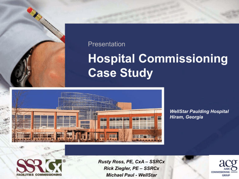
Presentation Hospital Commissioning Case Study WellStar Paulding Hospital Hiram, Georgia Rusty Ross, PE, CxA – SSRCx Rick Ziegler, PE – SSRCx Michael Paul - WellStar The Project • • • • • • $125 Million Replacement Hospital 295,000 SQFT, Eight Floors 56 beds, expandable to 112 beds (6th & 7th floors shelled) 40 ER exam rooms 4 surgical suites First Patient – March 28, 2014 Commissioning Scope • Review the energy model • Design reviews at 100% DDs and 100% CDs • Cx Specifications Commissioning Scope • Cx Plan • Shop Drawing Review • Prepare Installation Checklists monitor subs execution of these checklists • Prepare Functional Test Procedures, direct execution, document findings Commissioning Scope • Review: – T&B report – O&Ms – O&M staff training • Final Report • Opposed Season Testing • Warranty Meeting Commissioning Scope • • • • • • • • • Mechanical Systems Domestic Hot Water Fire Protection Fire Alarm Electrical Distribution Essential Electrical System (Emergency Power) Elevators Lighting Controls Building Envelope Mechanical systems • Multistack chiller (1,050 T) uses ground water loop when needed – Full Load testing to be conducted summer 2014 – Primary mode is simultaneous heating and cooling Mechanical systems • • • • Desiccant AHUs serve Surgery DOAS units serve multiple AHU systems Air valves on supply and return in OR systems 412 Tons of air-cooled Chillers serve DOAS units Energy Model Review • Energy Star Target Score: 94 • Model not updated for 100% CD design • Walls sections in model don’t match design • Insulation in roof in model different from design • Roof deck design (thickness) ≠ model Energy Model Review • Thermal resistance of windows over estimated in the model • Sun shade sizing differ between mode and design • DOAS, AHU and exhaust fan power understated in model vs 100% CDs • AHU SAT reset schedule in the EM ≠ the design Energy Model Review • Energy model over estimates unoccupied operating timeframe, thus under estimating energy usage 95% CD Plan Review - Mechanical • No detail provided for piping propane (secondary fuel) to steam boilers 95% CD Plan Review - Mechanical • No conditioned air in main electrical room • Plans did not indicate all isolation valves and flushing connections in Ground Loop system or at the Heat Pump Chiller • No SOO defined for atrium smoke evacuation function • No SOO for VAV boxes in kitchen tracking variable flow in range hood exhaust and dishwasher exhaust 95% CD Plan Review - Mechanical • Incomplete or missing SOO for stairwell pressurization and elevator shaft smoke vent • Purging and pressure testing procedures for ground loop piping not defined in the specifications 95% CD Plan Review - Electrical • No lighting controls SOO provided • No lighting controls specification included • Obstruction lighting control not defined, no photocell shown • Initiation of stairwell pressurization not defined • Electrical riser diagram, 4 dry type transformer shown fed from incorrect panels • 13 Panel schedules omitted from drawings • No IR scanning windows in some SWGR 95% CD Plan Review - Electrical • BOD states emergency generators shall be bi-fuel. Specifications do not require this capability. • “Pole” requirements for shunt trip breakers serving loads under kitchen hoods not identified in panel schedule Findings – HVAC Hydronics • CHW flow required for AHUs greater that CHW system output. (Strainers were loaded, had to be cleaned 3 times over course of FPTs) • Surgery Unit and AHUImaging not able to maintain DAT 55º with CHS @ 42º. (Strainers) Findings - BAS • OR AHU SAT controlled by 3 factors. Design sequence changed to insure SAT did not rise above desired conditions. – SAT – Dew point control – Temperature reset in unoccupied mode • OR pressure control incorrect (setpoints incorrect) • OR pressure alarms did not alarm when rooms negative (programming) • Critical zone reset for SP setpoint not programmed for Surgery system Findings - BAS • Surgery AHU Return Air SP safety tripped 5x when in un-occupied mode (added sensors) • DOAS and AHU SP control initially caused tripping of both systems on SP alarms (programming - rate of operation of control dampers) • HWPs and CHWPs did not operate in parallel (ramped individually in series) • Lag HWP and CHWP did not cycle off as load reduced Findings - BAS • SAT reset based on dew point not programmed • Humidifier not able to control to setpoint (programming) • DOAS filter alarms not programmed • Isolation Room alarms failed to alarm (programming) Findings - BAS • Isolation exhaust stand-by fan does not start when “lead” fan fails (N+1 programming) Findings - BAS • Graphics incomplete and/or inaccurate Findings - BAS • No time of use schedule programmed for boilers (3 total, 1 stand-by) • No communication between FO system and BAS • Sensors defective (MAT) • Domestic Booster pump alarms not programmed • Domestic Hot water alarms not programmed Findings – Fire Alarm System/ Life Safety • Dry Pipe system annunciation did not identify area protected • Inoperable tamper switches on A/S control valves • Elevator recall programming incorrect Findings – Lighting Controls • • • • Occupancy sensors not programmed Occupancy sensors would not time out Lighting controls not programmed Sensors blocked by OFE Findings – Emergency Power • Load Demand control setpoint initially set too low (operated 2 gensets when load required 1) • Day Tank FO return pump did not operate when high level alarm activated (G1) • FO return pump not operable (G2) • Priority Loads and Load Demand functions operated correctly MEP Lessons Learned • Ready to test – Despite scheduling, not ready to test – Programming incomplete, incorrect setpoints – Conflict between incomplete state and need to finish prior to occupancy • Controls associated with OR AHUs and OR space controls • Restart of AHUs on Emergency Power Project Timeline Enclosure Commissioning Environmental Separation • • • • • • Control heat flow Control airflow Control vapor flow Control rain Control groundwater Control light and solar radiation • Control noise and vibration • Control insects, rodents, and vermin • Control fire • Provide strength and rigidity • Be durable Owner’s Project Requirements • Design life of at least 50 years • No systemic water leaks, all leaks resolved prior to occupancy • Whole building air leakage rate of 0.1 cfm/sf @ 75 Pa • Slight positive pressure • Intent is to have continuous air, water, and thermal protection Design Phase • • • • Owner’s Project Requirements Two Design Reviews Specification Development Review of Energy Model Design Phase Pre-Construction Phase • Submittal and shop drawing reviews • Mock-up construction and testing • Update to functional performance test plan Mock-up Mock-up Mock-up Mock-up Summary • • • • • • Water leakage at window collar flashings Masonry tie air leakage at one location Whole mock-up air leakage testing pass Significant air leakage at roof to wall interface Curtain wall water leaks Retesting and next steps Construction Phase Construction Phase Construction Phase Construction Phase Questions
