Step-by-step plan of PCB assembly
advertisement
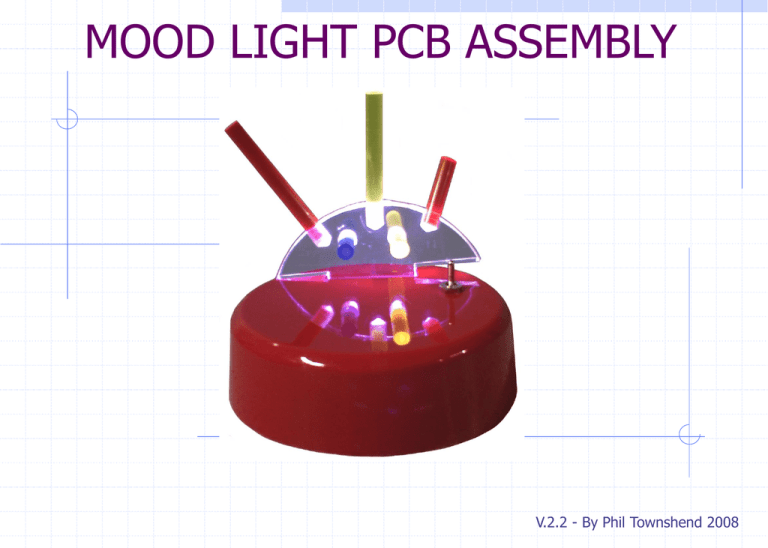
MOOD LIGHT PCB ASSEMBLY V.2.2 - By Phil Townshend 2008 ASSEMBLING THE PCB Hold up the PCB as shown below – try to locate the holes shown RESISTORS The first component is a resistor value 1Kohm, (brown, black, red). It is not important which way round it goes. RESISTORS The next 2 resistors are 22 ohms, (red, red, black). RESISTORS The last 2 resistors are both 47 ohms, (yellow, violet, black). IC HOLDER Insert the IC holder with the notch at the top as shown below. CAPACITOR The first capacitor is 100nF in value (104 written on it). It can be inserted either way round. CAPACITOR C2 must be inserted the correct way round. The longer lead is the positive one. Insert into the top hole with the silver stripe downwards. Positive Longer Leg MULTICOLOUR LEDs Flat side D1 must be inserted with the flat section on the rim facing right. This is normally the red/blue type. Insert them most of the way into the PCB. MULTICOLOUR LEDs D2 must be inserted the same way – this is the red/green type. You can put either LED in either place, it just means the colours cycle in reverse. FUNCTION SWITCH Strip about 8-10mm of insulation from a 100mm of wire and twist the strands together. Make another, then insert them into the PCB and solder. Feed the wires back through the PCB as shown to prevent them breaking. POWER LEADS Connect a single red wire about 150mm long to the top hole and solder. Feed the black wire from the battery clip, UP through the large hole first, then solder. SWITCHES There are 2 switches – the toggle switch for power and the push-to-make switch for the function. Connect as shown below. INTEGRATED CIRCUIT Finally insert the IC making sure the notch is at the top. Try not to bend the pins and ensure they are all inserted correctly. ASSEMBLY NOTES Both LEDs should light up red to start with. If they are green or blue, then the flat rim is facing the wrong way and colours will not be displayed correctly. The LED should be unsoldered using a de-solder pump, or by carefully heating up all 3 pads at once. Then rotated 180º and re-soldered. Clear the holes before inserting them. Another way to identify the orientation of the LEDs is that the shortest leg faces left. Common faults are pads shorted with solder bridges. Carefully use an iron or de-solder pump to clear them. If only one LED comes on and stays on, the IC is the wrong way round. Disconnect power immediately and insert the IC correctly. The maximum voltage the circuit can handle is 5v. After this outputs on the IC start to struggle and above 6v will destroy the IC completely.
