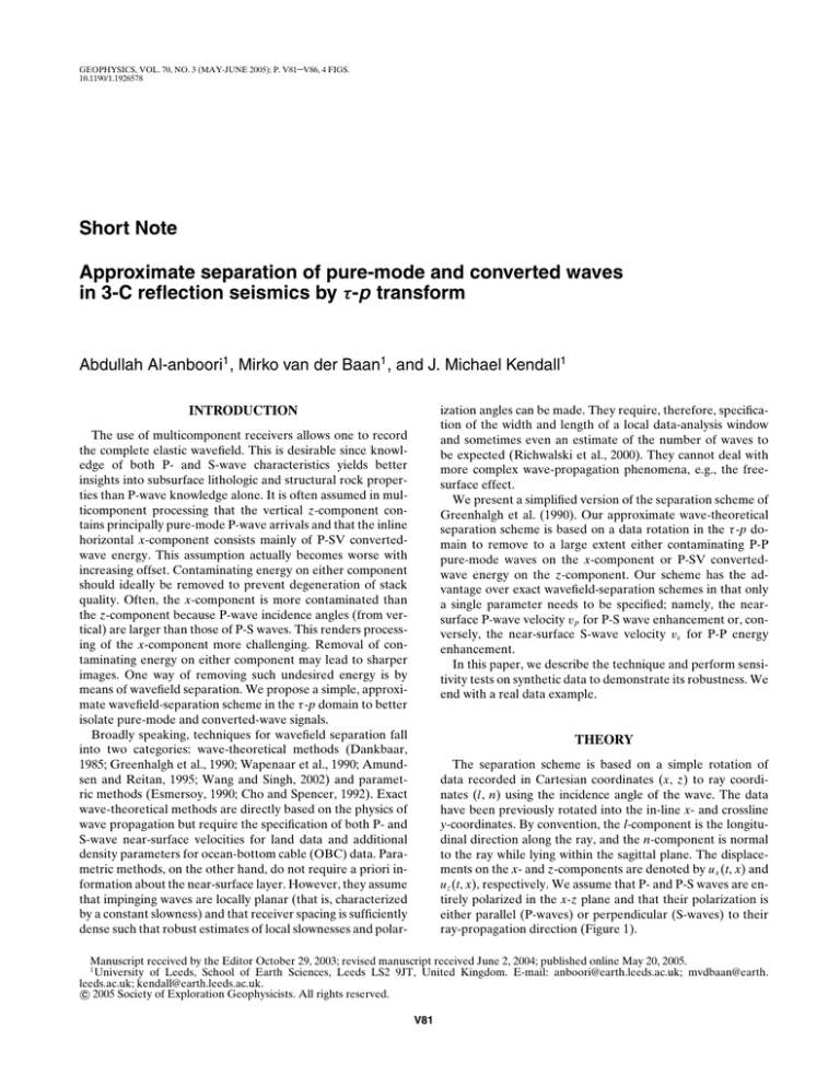
GEOPHYSICS, VOL. 70, NO. 3 (MAY-JUNE 2005); P. V81–V86, 4 FIGS.
10.1190/1.1926578
Short Note
Approximate separation of pure-mode and converted waves
in 3-C reflection seismics by τ -p transform
Abdullah Al-anboori1 , Mirko van der Baan1 , and J. Michael Kendall1
ization angles can be made. They require, therefore, specification of the width and length of a local data-analysis window
and sometimes even an estimate of the number of waves to
be expected (Richwalski et al., 2000). They cannot deal with
more complex wave-propagation phenomena, e.g., the freesurface effect.
We present a simplified version of the separation scheme of
Greenhalgh et al. (1990). Our approximate wave-theoretical
separation scheme is based on a data rotation in the τ -p domain to remove to a large extent either contaminating P-P
pure-mode waves on the x-component or P-SV convertedwave energy on the z-component. Our scheme has the advantage over exact wavefield-separation schemes in that only
a single parameter needs to be specified; namely, the nearsurface P-wave velocity vp for P-S wave enhancement or, conversely, the near-surface S-wave velocity vs for P-P energy
enhancement.
In this paper, we describe the technique and perform sensitivity tests on synthetic data to demonstrate its robustness. We
end with a real data example.
INTRODUCTION
The use of multicomponent receivers allows one to record
the complete elastic wavefield. This is desirable since knowledge of both P- and S-wave characteristics yields better
insights into subsurface lithologic and structural rock properties than P-wave knowledge alone. It is often assumed in multicomponent processing that the vertical z-component contains principally pure-mode P-wave arrivals and that the inline
horizontal x-component consists mainly of P-SV convertedwave energy. This assumption actually becomes worse with
increasing offset. Contaminating energy on either component
should ideally be removed to prevent degeneration of stack
quality. Often, the x-component is more contaminated than
the z-component because P-wave incidence angles (from vertical) are larger than those of P-S waves. This renders processing of the x-component more challenging. Removal of contaminating energy on either component may lead to sharper
images. One way of removing such undesired energy is by
means of wavefield separation. We propose a simple, approximate wavefield-separation scheme in the τ -p domain to better
isolate pure-mode and converted-wave signals.
Broadly speaking, techniques for wavefield separation fall
into two categories: wave-theoretical methods (Dankbaar,
1985; Greenhalgh et al., 1990; Wapenaar et al., 1990; Amundsen and Reitan, 1995; Wang and Singh, 2002) and parametric methods (Esmersoy, 1990; Cho and Spencer, 1992). Exact
wave-theoretical methods are directly based on the physics of
wave propagation but require the specification of both P- and
S-wave near-surface velocities for land data and additional
density parameters for ocean-bottom cable (OBC) data. Parametric methods, on the other hand, do not require a priori information about the near-surface layer. However, they assume
that impinging waves are locally planar (that is, characterized
by a constant slowness) and that receiver spacing is sufficiently
dense such that robust estimates of local slownesses and polar-
THEORY
The separation scheme is based on a simple rotation of
data recorded in Cartesian coordinates (x, z) to ray coordinates (l, n) using the incidence angle of the wave. The data
have been previously rotated into the in-line x- and crossline
y-coordinates. By convention, the l-component is the longitudinal direction along the ray, and the n-component is normal
to the ray while lying within the sagittal plane. The displacements on the x- and z-components are denoted by ux (t, x) and
uz (t, x), respectively. We assume that P- and P-S waves are entirely polarized in the x-z plane and that their polarization is
either parallel (P-waves) or perpendicular (S-waves) to their
ray-propagation direction (Figure 1).
Manuscript received by the Editor October 29, 2003; revised manuscript received June 2, 2004; published online May 20, 2005.
1
University of Leeds, School of Earth Sciences, Leeds LS2 9JT, United Kingdom. E-mail: anboori@earth.leeds.ac.uk; mvdbaan@earth.
leeds.ac.uk; kendall@earth.leeds.ac.uk.
c 2005 Society of Exploration Geophysicists. All rights reserved.
V81
V82
Al-anboori et al.
Such a rotation is not easily implemented in the x-t domain because each trace contains multiple arrivals with timevarying incidence angles. However, a similar rotation can be
applied on τ -p gathers, Sx (τ , p) and Sz (τ , p), where data are
sorted into horizontal slowness p and intercept time τ (Stoffa
et al., 1981). The incidence angle θ can be computed from the
horizontal slowness p using Snell’s law if we assume that a
thin, laterally homogeneous, near-surface layer exists. That is,
θ = sin−1 (pv1 ), where v1 is the near-surface velocity of the considered wave mode. The gathers Sx (τ , p) and Sz (τ , p) correspond to the τ -p transformed shot gathers ux (t, x) and uz (t, x),
respectively. The gathers Sx (τ , p) and Sz (τ , p) are then rotated by the incidence angle θ to ray-parallel Sl (τ , p) and rayperpendicular Sn (τ , p) gathers using a rotation matrix:
Sn (τ, p)
Sl (τ, p)
=
cos θ
sin θ
− sin θ
cos θ
Sx (τ, p)
Sz (τ, p)
.
(1)
The advantage of this approach is that the appropriate rotation angle depends only on the wave mode but does not vary
over time for a given constant-slowness trace. We now require
only knowledge of the mode of the detected arrival (i.e., P-P
or P-S waves) so that an exact separation scheme can be devised that depends on both the near-surface P-wave, vp , and
S-wave, vs , velocities and, additionally, density for OBC data
(Wang and Singh, 2002).
On the other hand, we could assume that all recorded energy consists of pure-mode P-P arrivals only and use the nearsurface vp to determine the P-wave rotation angle θp using
Snell’s law. After rotation, the l-component will actually contain all P-wave energy plus some converted waves. This rotated component is called the pass plane in the terminology of
Greenhalgh et al. (1990). The resulting n-component, called
the extinction plane, is free of P-P wave energy (Figure 1b).
An inverse τ -p transform applied on the n-component now
results in a converted-wave gather free of any interfering
P-P wave arrivals. The resulting displacements after inverse
τ -p transform on the l- and n-component are denoted ul (t, x)
and un (t, x), respectively.
Similarly, the same procedure using the near-surface
S-wave velocity vs yields improved P-P gathers (Figure 1c).
Only a single near-surface velocity is required for S/N enhancement, namely, vp to fully eliminate P-waves and vs to
fully reject S-waves. The scheme assumes an elastic, isotropic,
Z
a)
source
❋
b)
X
c)
l
Z
X
SV
SV
where qp and qs denote the vertical P- and S-wave slownesses
and are given by qp = (vp−2 − p 2 )1/2 and qs = (vs−2 − p 2 )1/2 .
It can be shown from equation 2 that the separation quality decreases with increasing slowness but depends also on the
actual vp /vs ratio. The quality increases with decreasing vp /vs
ratio. For instance, more than 90%
√ of the amplitudes is recovered for p < 0.5 s/km, vp /vs = 3, and vp = 1.6 km/s. This
corresponds to P-wave incidence angles less than 53◦ and Swave angles up to 28◦ and, therefore, offset/depth ratios of 2.7
and 1.8, respectively, for a one-layer medium.
APPLICATION TO SYNTHETIC DATA
P
θP
P
P
uP ,l
uS,n
=
= cos(θp − θs ) = vp vs qp qs + p2 , (2)
uP ,tot
uS,tot
l
Z
P
and homogeneous surface layer and negligible free-surface effects. Free-surface effects of incident P-S waves are much less
pronounced than those of P-waves because of steeper incidence angles. Fortunately, free-surface effects are most dominant for large offset/depth ratios which, in practice, are nearly
always muted out. The separation scheme is therefore applicable to a laterally inhomogeneous anisotropic earth with
an overlying homogeneous isotropic surface layer. However,
wavefield separation is performed on the final wave mode as
recorded at the receiver level, i.e., locally converted waves are
not extracted unless they arrive as S-waves at the surface.
Our approach is similar to the one proposed by Greenhalgh et al. (1990) except that they use the same rotation technique as a preprocessing step to determine the pass plane,
followed by a linear polarization filter to remove any remaining unwanted energy. The latter step is related to parametric
wavefield-separation techniques and suffers from the same inconveniences. We, on the other hand, content ourselves with
the extinction plane to approximately separate P-P and P-S
waves at the surface.
The separation technique does not recover the entire
incident-wave amplitude except at vertical incidence (i.e., zero
slowness) because of the nonorthogonality of the P- and P-S
wave particle motion for identical horizontal slownesses. The
performance of the separation scheme actually degrades with
increasing slowness p and, therefore, offset. The amount of
recovered energy in the extinction plane can be computed analytically (Greenhalgh et al., 1990). The ratio of the recovered
P-wave amplitude uP ,l as projected on the l-axis to the total incident P-wave amplitude uP ,tot and the ratio of the recovered
S-wave amplitude uS,n on the n-axis to the total incident P-S
wave amplitude uS,tot are both given by cos(θp −θs ) (Figures 1b
and 1c). That is,
θS
X
SV
n
n
Figure 1. (a) P-P and P-S wave ray paths and their polarization
vectors for a simple one-layer model. The data is rotated from
general Cartesian coordinates (x, z) to ray coordinates (l, n)
using (b) the near-surface P-wave velocity vp or (c) the S-wave
velocity vs . The l- and n-components are, respectively, along
and perpendicular to the ray direction while remaining within
the sagittal plane. The angles θp and θs indicate the P-P- and
P-S-wave incidence angles, respectively.
An isotropic 1D earth model composed of six layers is employed to study the performance of our separation method.
The velocities are monotonically
√ increasing with depth with a
roughly constant vp /vs ratio of 3. The near-surface vp and vs
are 1.6 km/s and 0.9 km/s, respectively. All common-shot gathers (CSGs) are computed by ray tracing (Guest and Kendall,
1993) using a P-wave source with maximum offsets of 4 km
and a receiver spacing of 25 m. A Ricker wavelet with a dominant frequency of 20 Hz is used. Only primary P-P and P-S
wave reflections are computed.
Figure 2 shows, step by step, application of the scheme to
the CSG ux and uz to remove P-wave contamination on the
Approximate Wavefield Separation
x-component using the near-surface P-wave velocity vp . First,
uz and ux are transformed to the τ -p domain, producing the
gathers Sz and Sx . Then, these are rotated to longitudinal and
normal components Sl and Sn using Snell’s law and expression
1. An inverse τ -p transform produces the
new shot gathers ul (x, t) and un (x, t). As
predicted, the reconstructed shot gather
un is free of P-wave contamination (compare Figures 2b and 2h). Even overlapping
P-S and P arrivals are well separated. Using vs instead of vp produces a new P-P
wave shot gather ul (x, t) that is free of P-S
wave contamination.
V83
percentage error and slowness. However, for a given absolute
vp percentage error, overestimated vp leaks more P-wave energy than underestimated vp . It also depends less significantly
on the vp /vs ratio as P-wave spillover increases with increasing
SENSITIVITY AND
ACCURACY TESTS
Sensitivity tests are carried out to determine to what accuracy the near-surface
velocity needs to be specified and to investigate the effects of lateral velocity gradients and anisotropy in the first layer.
Relative error in vp and vs
It is not always easy to accurately determine the near-surface velocities vp and
vs . An incorrect estimate of vp causes
P-wave spillover on the n-component as
a result of incorrect estimation of the
P-wave incidence angle θp . The P-wave
spillover can be analytically calculated
as a function of percentage error in vp .
The amount of P-wave spillover on the
n -component uP ,n as a fraction of uP ,tot
created by an erroneous velocity vp is
given by
uP ,n
= sin(θp − θp )
uP ,tot
= vp vp p(qp − qp ),
(3)
where θp is the erroneous incidence angle of the P-wave and qp = (vp−2 − p 2 )1/2 .
Misspecification of vp also leads to an increase or decrease in S-wave energy recovered on the n-component, depending
on the sense of the error. The recovered
amount of S-wave energy uS,n is given
by expression 2 with θp replaced with θp .
Therefore, the amplitude ratio uP ,n /uS,n
indicates simultaneously how P-wave energy spills over and how S-wave energy
is changed on what otherwise would have
been a gather containing S-wave energy
only. It is given by
uP ,n
uS,n
=
uP ,tot vp p(qp − qp )
.
uS,tot vs qp qs + p2
(4)
Analysis of equation 4 shows that Pwave spillover increases with increasing vp
Figure 2. Illustration of the rotation procedure using the near-surface P-wave velocity
to remove P-waves. Shot gathers uz (a) and ux (b) are transformed to the τ -p gathers
Sz (c) and Sx (d), and rotated to longitudinal and normal components Sl (e) and Sn
(f). An inverse τ -p transform then produces the new shot gathers ul (g) and un (h).
Nearly all P-wave energy has been removed from the extinction plane un [compare
(b) and (h)]. Pn and PSn denote primary reflections/conversions of the nth interface,
respectively. Reflections and conversions of the bottom of the weathering layer are
not shown (P1 and PS1).
V84
Al-anboori et al.
vp /vs ratio. For instance, √
errors up to −25% and +20% in vp
(for p = 0.4 s/km, vp /vs = 3, vp = 1.6 km/s, and uP ,tot = uS,tot )
produce 20% P-wave spillover. The effect of vp error on the
separation quality is illustrated in Figure 3 using a +20% error in vp . P-waves (particularly P2 ) spillover onto the P-S section increases with increasing offset (or p), as predicted by
equation 4. However, the resulting shot gather contains significantly fewer P-waves than the original x-component.
The near-surface velocity vs is even harder to estimate in
practice. The equation for S-wave spillover, uS,l /uP ,l , on the
l -component caused by an error in vs is calculated in an analogous fashion; the result is the same as expression 4 except the
P- and S-wave subscripts are reversed. Like P-wave spillover,
S-wave spillover exhibits similar relations between percentage error, slowness, and vp /vs ratio. However, the separation
scheme is less sensitive to vs error than to vp error since vs
is always smaller than vp . √
Errors up to −45% and +50% in vs
(for p = 0.4 s/km, vp /vs = 3, vp = 1.6 km/s, and uP ,tot = uS,tot )
yield approximately 20% S-wave spillover.
Anisotropic and laterally heterogeneous surface layers
Our scheme assumes a thin isotropic layer at the surface
where the velocity is laterally constant. We performed various
tests to determine how separation results are affected if this
assumption is violated. Lateral P-wave velocity gradients up
to 0.25 s−1 were introduced in the upper part of the six-layer
model. Results show that the separation quality decreases with
an increasing gradient, but P-P or P-S wave contamination is
always significantly reduced in the resulting shot gathers for
P-wave gradients less than approximately 0.125 s−1 .
The effect of elliptical P-wave anisotropy in the nearsurface layer was also examined. Tests show that the separation quality degrades with increasing anisotropy but remain
reasonable for values up to 20% anisotropy. In the case of
elliptical anisotropy, the vertical and horizontal P-wave velocities differ, but moveout remains hyperbolic (Thomsen,
1986). The effect on nonelliptical anisotropy is harder to antic-
ipate but probably restricts performance to somewhat smaller
amounts of anisotropy.
APPLICATION TO REAL DATA
We examine the applicability of the separation scheme to
real data from western Canada. The data set was acquired
over a sedimentary basin where the geologic structure is
roughly flat. Only basic processing was applied on the shot
gathers: top mute, bandpass filtering, and scaling of the amplitudes with time squared to approximately correct for geometric spreading. The latter was done to preserve the relative
amplitude ratio between the x- and z-components.
The surface layer vp was obtained from moveout analysis of
both the direct wave and the first P-reflection, and was found
to be 1.7 km/s. The near-surface vs was more difficult to determine because the low S/N ratio on the x-component rendered
the first P-S conversion invisible. After a series of performance
tests, vs was set to 0.9 km/s.
Figure 4 displays the original z- and x-component and the
enhanced P-wave and P-S CSGs after separation. Both the
P-P and P-S CSGs show a significant increase in the S/N
ratio, and many events are stronger and more clearly defined.
Contamination of surface waves and noncoherent noise is reduced because the τ -p transform acts as a dip filter. This, in
combination with the presence of an antialiasing filter (Moon
et al., 1986) in the forward and inverse τ -p transform, leads
to smoother events. The resulting P-P gather displays a higher
increase in S/N ratio than the P-S gather. One drawback of
the method is that the S/N ratio in one component may be affected by the S/N ratio in the other one. For instance, energy
from the z-component (e.g., at x = 2 km and t = 1.1 s) leaked
into the P-S gather after separation.
The leakage of P-waves into the P-S gather could also be
caused by the presence of nonlinearly polarized P- and Swaves. Indeed, hodogram analysis shows that both wave types
display some elliptical particle motion. This could be the result
of multipathing and overlapping arrivals such as local conversions at the surface. In practice, this effect is most prominent
at large offset/depth ratios that are normally muted out.
DISCUSSION AND PRACTICAL REQUIREMENTS
Figure 3. Resulting P-S shot gather after overestimating the
near-surface vp by 20%. More P-wave energy has leaked into
the new shot gather, but the S/N ratio is still significantly better
than the original x-component (compare with Figures 2b and
2h).
The near-surface needs to be approximately laterally homogeneous for our technique to work well. In addition, care
should be taken to ensure that neither processing nor acquisition affects the relative ratio between the horizontal and vertical ground displacement. The latter condition requires care in
applying gain methods to ensure that this ratio is not changed.
For instance, automatic gain control should not be used prior
to wavefield separation. Furthermore, relative horizontal and
vertical geophone coupling, sensitivity, and calibration all affect the performance. An elevation correction also needs to be
applied.
Single geophone recording (one geophone per recording
channel) is desirable. The separation quality may degrade if
geophone groups are used without further correction, since
this again affects the polarization directions. See Dankbaar
(1985) for a thorough discussion.
Our scheme is based on a rotation by the incidence angle at
the receiver and, therefore, uses the receiver slowness. Hence,
Approximate Wavefield Separation
V85
Figure 4. Application on real data. Original shot gathers z-component (a) and x-component (b) and resulting shot
gathers P-P (c) and P-S (d) after separation using, respectively, the near-surface vs and vp velocities. In particular, the
P-P section shows a significantly improved S/N ratio. Note that time scales are different on top and bottom.
it needs to be applied on CSGs instead of common-midpoint
or common-receiver gathers.
The use of a constant velocity in the separation scheme can
be a limitation for seismic lines that run over areas where the
near surface exhibits large lateral variations in elastic properties. However, mild lateral variation in the surface layer within
a spread length can be accounted for by rescaling the data
during the τ -p transform [see Greenhalgh et al. (1990) for
details].
CONCLUSIONS
Our approximate τ -p domain wavefield-separation scheme
yields significantly higher S/N ratios in both P-P and P-S
shot gathers of both synthetic and real data. This is achieved
by a simple rotation based on a single near-surface velocity,
thereby effectively removing most energy from contaminating
modes. Our approximate separation scheme gives us the freedom of choice to remove either the P-waves or, conversely,
superposed converted waves from a multicomponent data set
by specifying a single velocity. This is in strong contrast to exact wavefield-separation schemes that attempt to solve both
situations simultaneously. These require the specification of
both P- and S-wave velocities and often density, with performance strongly depending on the accuracy of each single
parameter. Our scheme is applicable to a laterally inhomogeneous anisotropic earth with a homogeneous isotropic surface
layer. Sensitivity tests show that errors in the estimates of the
near-surface P- and S-wave velocities can be as much as 20%
and 45%, respectively, while still obtaining satisfactory results.
Also, reasonable results can be attained with near-surface elliptical anisotropy and lateral velocity gradients of as much as
20% and 0.125 s−1 , respectively.
ACKNOWLEDGMENTS
We thank Veritas for permission to use their seismic data
and Petroleum Development Oman (PDO) for financial support. We also thank S. Greenhalgh and two anonymous reviewers for their constructive comments.
V86
Al-anboori et al.
REFERENCES
Amundsen, L., and A. Reitan, 1995, Decomposition of multicomponent sea-floor data into upgoing and downgoing P- and S-waves:
Geophysics, 60, 563–572.
Cho, W. H., and T. W. Spencer, 1992, Estimation of polarization and
slowness in mixed wavefields: Geophysics, 57, 805–814.
Dankbaar, J. W. M., 1985, Separation of P- and S-waves: Geophysical
Prospecting, 33, 970–986.
Esmersoy, C., 1990, Inversion of P and SV waves from multicomponent offset vertical seismic profiles: Geophysics, 55, 39–50.
Greenhalgh, S. A., I. M. Mason, E. Lucas, D. Pant, and R. T. Eames,
1990, Controlled direction reception filtering of P- and S-waves in
τ -p space: Geophysical Journal International, 100, 221–234.
Guest, S., and M. Kendall, 1993, Modelling seismic waveforms in
anisotropic inhomogeneous media using ray and Maslov asymptotic
theory: Applications to exploration seismology: Canadian Journal
of Exploration Geophysics, 29, 78–92.
Moon, W., A. Carswell, R. Tang, and C. Dillistone, 1986, Radon transform wave field separation for vertical seismic profiling data: Geophysics, 51, 940–947.
Richwalski, S., K. Roy-Chowdhury, and J. C. Mondt, 2000, Practical aspects of wave-field separation of two-component surface seismic data based on polarisation and slowness estimates: Geophysical
Prospecting, 48, 697–722.
Stoffa, P. L., P. Buhl, J. B. Diebold, and F. Wenzel, 1981, Direct mapping of seismic data to the domain of intercept time and ray parameter — A plane-wave decomposition: Geophysics, 46, 255–267.
Thomsen, R. H., 1986, Weak elastic anisotropy: Geophysics, 51, 1954–
1966.
Wang, Y., and S. C. Singh, 2002, Separation of P- and SV-wavefields
from multicomponent seismic data in the tau-p domain: Geophysical Journal International, 151, 633–661.
Wapenaar, C. P., P. Hermann, D. J. Verschuur, and A. J. Berkhout,
1990, Decomposition of multicomponent seismic data into primary
P- and S-wave responses: Geophysical Prospecting, 38, 633–661.


![[ ] Physics 617 Problem Set 6 Due Friday, Mar 25](http://s2.studylib.net/store/data/011584405_1-35356220a00f6666cf75b132b3602d20-300x300.png)
