Homework 5
advertisement
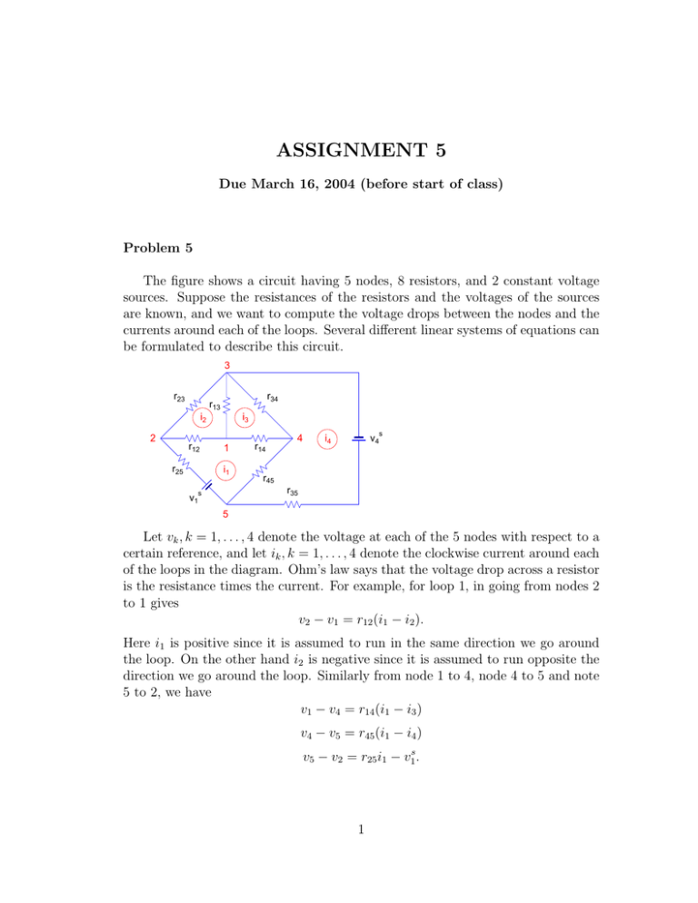
ASSIGNMENT 5 Due March 16, 2004 (before start of class) Problem 5 The figure shows a circuit having 5 nodes, 8 resistors, and 2 constant voltage sources. Suppose the resistances of the resistors and the voltages of the sources are known, and we want to compute the voltage drops between the nodes and the currents around each of the loops. Several different linear systems of equations can be formulated to describe this circuit. 3 r23 r34 r13 i2 2 r12 r25 i3 1 i1 r14 4 s i4 v4 r45 r35 s v1 5 Let vk , k = 1, . . . , 4 denote the voltage at each of the 5 nodes with respect to a certain reference, and let ik , k = 1, . . . , 4 denote the clockwise current around each of the loops in the diagram. Ohm’s law says that the voltage drop across a resistor is the resistance times the current. For example, for loop 1, in going from nodes 2 to 1 gives v2 − v1 = r12 (i1 − i2 ). Here i1 is positive since it is assumed to run in the same direction we go around the loop. On the other hand i2 is negative since it is assumed to run opposite the direction we go around the loop. Similarly from node 1 to 4, node 4 to 5 and note 5 to 2, we have v1 − v4 = r14 (i1 − i3 ) v4 − v5 = r45 (i1 − i4 ) v5 − v2 = r25 i1 − v1s . 1 Kirchoff’s voltage law says that the sum of the voltage differences around each loop is zero. Therefore around loop 1 we have (v2 − v1 ) + (v1 − v4 ) + (v4 − v5 ) + (v5 − v2 ) = r12 (i1 − i2 ) + r14 (i1 − i3 ) + r45 (i1 − i4 ) + r25 i1 − v1s = 0. Thus we have the equation (r25 + r12 + r14 + r45 )i1 − r12 i2 − r14 i3 − r45 i4 = v1s . (1) Similarly for loop 2, 3 and 4, we have −r12 i1 + (r23 + r12 + r13 )i2 − r13 i3 = 0, (2) −r14 i1 − r13 i2 + (r14 + r13 + r34 )i3 − r34 i4 = 0, (3) −r45 i1 − r34 i3 + (r35 + r45 + r34 )i4 = v4s . (4) These 4 equations, taken in this order, yield the following 4 by 4 linear system: Ri = v, (5) where R is the resistance matrix r25 + r12 + r14 + r45 −r12 −r14 −r45 −r12 r23 + r12 + r13 −r13 0 −r14 −r13 r14 + r13 + r34 −r34 −r45 0 −r34 r35 + r45 + r34 Since the resistances are all non-negative, R is diagonally dominant. Therefore row-pivoting is not needed for this matrix. For this homework: 1. Assume that the resistors all have a resistance of 1 Ω, and the constant voltage sources are given by v1s = v4s = 15 V . Use LU-factorization without pivoting to obtain the solution for the current vector i in amperes. 2. Next modify the circuit so that r14 has a new value of 6 Ω. Perform a rank-one update of the solution you to find the new current vector. 3. Obtain the current using MATLAB’s own linear system solver and compare with what you get in part 2. Show all your results and submit a hard-copy of your MATLAB program as well. 2
