Product Data Sheet
SD 1506-2E04
February 2011
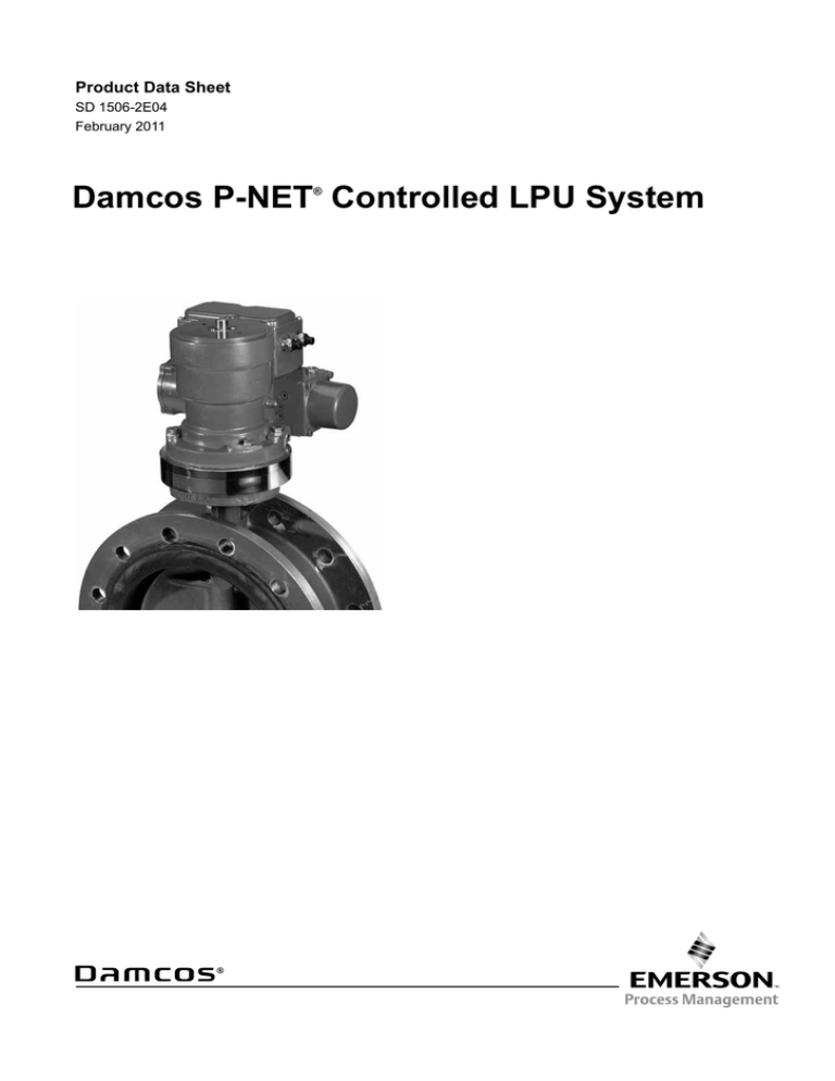
Damcos P-NET Controlled LPU System
®
Product Data Sheet
Damcos P-NET
SD 1506-2E04
February 2011
®
Introduction
The P-NET controlled LPU is specially developed to
be integrated in complete MTM (Marine Tank Management) systems, which includes:
The P-NET LPU is equipped with 2 optocoupler
inputs for controlling the valve, and 2 relay outputs
and an analogue output for position feedback signals.
The P-NET controlled LPU can be used as a standalone unit without being connected to P-NET. In this
case it is controlled from external inputs/outputs connected to simple push-buttons, lamps or e.g. a PLC
(Programmable Logistic Controller).
The LPU has built-in internal push-buttons and LEDs
to be used for commissioning/test of the unit.
Whether the LPU is controlled by the P-NET or by
external inputs/outputs, the built-in microprocessor
controls and manages the actual control. This ensures an optimal control of the LPU, which is never
overloaded.
-
Valve control and operation.
Pump control and operation.
Tank contents gauging and calculation.
Draft, trim and heel measurement and calculation.
- Interface to loading/stability computer.
- Interface to ISC (Integrated Ship Control) system.
The P-NET controlled LPU is fitted with a
P-NET fieldbus, enabling interconnection of the LPU
with other P-NET units, such as IO modules, display
units, controllers and work-stations for the shared
fieldbus P-NET.
MTM system layout
ECR
ECR Workstation
Crew Room
Bridge Room
Alarm Panel
Alarm Panel
Mounting Plate for
ECR Console
Alarm Panel
VISION
CPU
ALARM
PRINTER
602
620
622
600
OPTION
? x Digital Input (PD622)
? x Digital Output (PD620)
Modbus to IMACS (OPTION)
PUMP CONTROL
Aux. Engine 1
? x Digital Input (PD622)
? x Digital Output (PD620)
? x Valve Control (PD527)
? x Pump/Ventilation (PD621)
? x Tank Measurements PD640)
MAS2600
MAS2600
MAS2600
MAS2600
LPU BUS (P-Net)
2x2x0,75mm2 RS485 Bus
Main Engine 1
10" Local
Workstation
Modbus RS485
602
600
600
Inputs/Outputs
602
600
600
Engine Control Room 2 (FOR)
Modbus RS485
I/O Panel 1
Power Cable 230V
1x1,5mm2 (Max 15 LPU’s)
2
10" Local
Workstation
Inputs/Outputs
PUMP CONTROL
Engine Control Room 1 (AFT)
Redundant EtherNet Ring
Power Cable 230V
1x1,5mm2 (Max 15 LPU’s)
I/O Panel 1
LPU BUS (P-Net)
2x2x0,75mm2 RS485 Bus
Main Engine 1
Aux. Engine 1
? x Digital Input (PD622)
? x Digital Output (PD620)
? x Valve Control (PD527)
? x Pump/Ventilation (PD621)
? x Tank Measurements PD640)
Product Data Sheet
SD 1506-2E04
February 2011
Damcos P-NET
®
General description
Complete MTM systems can be designed on the
basis of the P-NET LPU. The MTM systems are
designed to match needs and requirements of each
individual ship with respect to LPU location, cable
installation, safety, control of other machinery, data
acquisition and control of other measuring points,
operation facilities centralised and decentralised.
Each P-NET LPU is connected to a combined
communication/24 VDC supply cable (4-Wire PNET) and an AC supply cable. This offers the user
the possibility of viewing status from LPU, should the
AC supply fail.
This provides a very flexible installation in which
both 4-Wire P-NET and VAC supplies are separated
in suitable numbers of segments irrespectively of the
ship’s layout, LPU location and the required safety.
Galvanic separation of 4-Wire P-NET bus segments
is possible by means of P-NET repeaters, each with
3 galvanically separated P-NET. The 3 P-NET could
be used e.g. in connection with a small section at
starboard/port-side and in connection with a superior
network. This means that a partial failure will not
affect the remaining network. The separation of the
AC supply can e.g. be done by connecting each segment via a separate fuse.
Supervision/operation of the LPU can take place
from a P-NET master, i.e. a controller or workstation.
These units can be installed on the P-NET wherever
operation is needed, e.g. on the bridge, in the cargo
control room, engine control room or locally in interface panels.
The connected controllers/workstations can be
configured to be redundant in relation to each other.
This feature being an additional safety for the crew
should any unit fail.
Interlocks for the connected controllers/work
stations can be implemented. In this way a certain
group of LPUs and attached equipment are operated
from one location only, and simultaneous operation
from more locations is prevented.
An on-line connection can be established to the
vessel’s ISC system for transfer of commands, status, alarms etc.
The LPU built-in microprocessor intensively monitors
the unit, including the following errors/alarms:
Program/RAM/EEPROM storage errors.
Watch dog run out (P-NET communication has stopped).
Pressure switch error.
Invalid position transmitter system.
Position (differs significantly from set point).
Low AC power.
Max run time (Motor and pump protection).
Motor overload (Motor and pump protection).
Max time (Valve moves too slowly).
Min time (Valve moves too fast).
Pressure (Hydraulic pressure not achieved, or has
fallen).
The following are measured and displayed:
-
Actual position analog feedback 0-100%.
On/Off feedback 0% (closed), 50 % (middle), 100 % (open).
Motor status (stopped, opening, closing).
Operation mode (P-NET®, Voltage input, Internal pushbuttons).
AC voltage.
DC voltage.
3
Product Data Sheet
Damcos P-NET
SD 1506-2E04
February 2011
®
The LPU can be controlled from a master in two
ways:
- Through transfer of a setpoint to the LPU, which takes over the actual control of the motor and stops when the wanted setpoint has been reached.
- Direct control: open/close/stop.
changed from P-NET. This is especially used for
protecting automated procedures.
Apart from being P-NET controlled, the LPU can
simultaneously be controlled locally from e.g. an
emergency control. From the connected controllers/
workstations it is possible to check whether the LPU
is locally opeated either by internal or by the external
pushbuttons. It is possible to have an alarm indication activated when the LPU is locally operated.
Another safety feature, “Block Setpoint” blocks the
LPU so the Setpoint cannot be
P-NET
LPU
P-NET
PCB diagram for local control
N
N
L 230 V AC
L
+24 V DC
A
B
Gnd
+24 V DC
A
B
Gnd
4-20mA
Common command
Close command
Open command
Common feed back
Closed feed back
Open feed back
15
14
13
12
11
10
9
8
7
6
5
4
3
2
1
Valve
position
+24 V DC
Closed
Close
Open
Open
Gnd
Features
- 100% protection and control of the LPU.
- One circuit board only for LPU–S and LPU–D, analog and ON/OFF feedback, P-NET and hard
wire voltage input controlled.
- Being a P-NET slave the P-NET LPU is an independent unit to be controlled directly from e.g. a workstation.
- All LPUs can operate simultaneously with a suit
able dimensioning of AC power supply.
- Random delay restart of the LPU-S after an AC voltage drop to prevent all LPUs from starting at the same time, thus avoiding drawing high starting current in the system.
- From the P-NET indication can be given how the LPU was operated the last time; internal/exter
nal pushbuttons or from the P-NET.
- From the P-NET change of Setpoint can be blocked.
- ”AutoCorrection” option (the LPU retakes its posi tion, and re-establishes pressure if it drops in open position on the LPU-S). This feature can be
disabled when no P-NET communication is
4
present, in order to allow emergency operation of the LPU if the P-NET fails.
Measurement of 24 VDC and VAC power suplies.
The unit is monitored even if the VAC supply falls out.
The presence of 24 VDC is displayed on the internal LEDs.
Prepared for future oil level gauging in the tank.
Good service/starting up facilities as the LPU.:
Can be operated directly from internal pushbut
tons. One-touch pushbuttons for opening or clos-
ing valves.
Has got indication on internal LEDs of position (Open, Closed, Intermediate) and alarm state if any.
If the pushbutton is not released, the signal is ignored.
Can be used as PLC/power controlled with sepa-
rate VAC power supply and 24VDC control input/
output, and ON/OFF and analogue position feed
back.
Product Data Sheet
SD 1506-2E04
February 2011
Damcos P-NET
®
Description
Apart from being controlled by the P-NET the LPU
can be used as a stand-alone unit without P-NET but
controlled by hardwired inputs/outputs (24 VDC supply must be connected). 24 V DC I/O can be used directly i.e. from PLC. P-NET is applied in connection
with end testing, for configuration and test only.
Control follows by means of voltage inputs. Position
feedback signal from relay outputs or a 4-20 mA
transmitter.
Also when hardwire controlled, a 100 % protection of
the LPU is achieved just as if it was controlled from
P-NET, as the control and supervision functions are
carried out by the built in microprocessor.
A galvanic separation of the position signals from the
DC supply can be established (except for the 4-20
mA output). Due to the separate AC supply all signal
transfers lie on 24 VDC level.
There are 4 possible controlling methods for the LPU
control inputs:
- PulseMode (only a pulse is needed either for opening or closing the valve).
- ActiveMode (LPU only moves while a continuous high signal for opening or closing is given, and automatically stops in end position).
DirectionModeOpen (a continuous high signal is given on only one input to select valve open).
DirectionModeClose (a continuous high signal is given on only one input to select valve closed).
In “DirectionMode” the LPU position (fully open or
fully closed) can be controlled from one 24 VDC
input, while the other input is used for enabling the
valve movement. The relay outputs are for ON/OFF
position indication. When the valve is < 3% open,
the closed output is high. When the valve is > 97%
open, the Open output is high. In intermediate positions, both inputs are low.
In case of a position indicator error (or if the 24V supply to the PCB (Printed Circuit Board) has fallen out),
both outputs are high. The analogue 4-20 mA output is
connected to the 0 from the 24V DC supply. The 4 mA
corresponds to 0% open, and 20 mA corres-ponds to
100% open. Position indicator error is indicated by an
output current of 0 mA.
P-NET
LPU
P-NET
PCB diagram for stand alone unit
N
N
L 230 V AC
L
+24 V DC
A
B
Gnd
+24 V DC
A
B
Gnd
4-20mA
Common command
Close command
Open command
Common feed back
Closed feed back
Open feed back
15
14
13
12
11
10
9
8
7
6
5
4
3
2
1
+24 V DC
Closed
Valve
position
Close
Open
Open
Gnd
Features
The following features can be added to the Hardwire
controlled P-NET LPU:
LPU is controlled by using one or two control inputs (open/close) and two feedback outputs (open/closed), and/or one analogue 4-20mA posi-
tion feedback output.
AutoCorrection option for hardwire controlled LPU also.
Has galvanic separation between control input and output and the 24VDC supply, except for 4-20 mA output which is to be connected to minus on the 24 VDC.
Is fitted with its own relays. Control inputs (open/
close) can directly be connected to the PLC (24 VDC).
5
Product Data Sheet
Damcos P-NET
SD 1506-2E04
February 2011
®
P-NET Fieldbus
®
The P-NET Fieldbus, first developed in 1983 and
since then applied on more than 10,000 installations
became 1996 European standard EN50170 Vol. 1
and in 2000 International standard IEC 61158 Part 4.
P-NET is based on the electric standard RS485
with a 2-wire twisted shielded cable. Today a 4-wire
twisted shielded cable, including both communication and 24 VDC supply can be used as well.
Each single P-NET segment can be up to 1,200
meter long. More P-NET segments can be linked
together by controllers with two P-NET ports.
The P-NET is a multi master network. To each segment totally up to 125 nodes (P-NET LPU, Interface
modules, controllers and workstations) can be connected, hereof max. 32 masters (Controllers, Workstations).
The P-NET Baud rate is 76.8 k corresponding to 300
transactions (questions and answer) per second.
Test and configuration tools
Test and configuration of the P-NET LPU to meet the
customers specifications takes place when the unit
is end tested in the factory with the valve.
This ensures a correct setup of the LPU, hereunder
actuator type1, indicator type2, max./min. time3, run
on4, calibration of feedback5 etc.
Fieldbus controlled
The programme ”Project” is used for set-up of
complete MTM systems, including all hardware
and software modules. From this programme there
is free access to all units connected to the P-NET
fieldbus. Therefore, it is also possible to change all
data settings in the LPUs and have them tested via
the P-NET fieldbus.
All data settings from the test incl. order number,
new-building number, yard, valve number etc. are
stored in a shared database. Data from one single
order can be exported to an order specific database
and applied for further test/configuration on board.
Settings for a specific valve are stored, and may be
restored into spare LPU PCB.
Hardwire controlled
The programme used for end test of a unit in the factory can be applied on board for test/configuration of
the P-NET LPU.
Position indication input signals
The position indicator is built into the pump block
with internal wiring from position indicator to the
circuit board mounted in the LPU electrical encapsulation (except for KFR). Potentiometer for analogue
position indication or 2 micro-switches for end-position indication are available.
The P-NET LPU is to be configured either to position
indicator type ON/OFF or analogue.
LPU with LED Postion Indicator
The LED indicator is powered from the 24VDC supply for the LPU electronics, via the internal position
indicator output relays in LPU circuit board. LED indicator can be used with either ON/OFF or ANALOG
position indicator as desired.
6
With analog position indicator, the LED will change
status over at 3% open valve and 97% open valve.
Product Data Sheet
SD 1506-2E04
February 2011
Damcos P-NET
®
Digrams for LPU with LED Postion Indicator
LPU P-NET with LED Indication - Option 1
High = 24V
Low = 0V
LPU P-NET with LED Indication - Option 2
Closed = 0-3% valve pos.
Open = 97-100% Valve pos.
7
Product Data Sheet
Damcos P-NET
SD 1506-2E04
February 2011
®
Electrical specification
AC power supply:
Voltage Nom.
220-230 V AC 50 or 60 Hz + 10% - 15%
Current
1.4 A (max. 4.0 A)
Interface:
4-wire P-NET
DC voltage:
Min.
12 V DC
Nom.
24 V DC
Max.
35 V DC
Power supply:
Min.
25 mA 12 V DC
Idle max.
70 mA 12 V DC
Max.
140 mA 12 V DC (incl. 20 mA output)
Min.
25 mA 24 V DC
Idle max.
70 mA 24 V DC
Max.
115 mA 24 V DC (incl. 20 mA output)
Min.
25 mA 35 V DC
Idle max.
70 mA 35 V DC
Max.
100 mA 35 V DC (incl. 20 mA output)
Inputs, 24 V (galvanic separation with opto-couplers):
V in Off
< 1.4 V DC
V in On
> 10.0 V DC
V in max.
45 V DC
Ri
10 k Ω
Outputs, galvanically isolated relays:
Imax.
1 A 30 V DC or 0.5 A 125 V DC
Analogue output, external 4 -20 mA:
Resolution
100 uA
Accuracy
2.5%
Output voltage
Vin/2-1 V
Update freq.
32 Hz
Duty/cycle:
Max.
30% for 10 minutes
Max. running time
5 minutes at 20°C
The Emerson logo is a trademark and service mark of Emerson Electric Co. Damcos and the Damcos logotype are registered trademarks of
Damcos A/S. All rights reserved. The contents of this publication are presented for information purposes only, and while effort has been made
to ensure their accuracy, they are not to be construed as warranties or guarantees, expressed or implied, regarding the products or services
described herein or their use or applicability. All sales are governed by our terms and conditions, which are available upon request. We reserve
the right to modify or improve the designs and specifications of our products at any time without notice. Damcos A/S accepts no responsibility
for any errors that may appear in this publication.
This product is developed and managed by:
Emerson Process Management
Damcos A/S
Aaderupvej 41
DK-4700 Naestved
T +45 5578 7200
F +45 5578 7272
© 2008 Damcos A/S
For global contacts:
www.EmersonProcess.com/mtm

