INSTRUCTION SHEET FOR PLUG/CONNECTOR WITH CONDUIT ADAPTER.
30 & 50 & 60 AMP DuraGard ® Devices (Conduit Adapter Kit)
(For use with metallic conduit only)
WARNING
CAUTION
Risk of electrical shock.
De-energize all power prior to installation or repair.
Use only copper or copper clad aluminum wire with
box mounted outlet or inlet. Use of other wire may
result in the connector failing in service.
APPLICATION
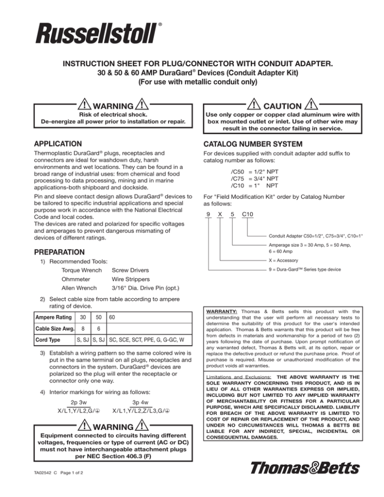
CATALOG NUMBER SYSTEM
Thermoplastic DuraGard ® plugs, receptacles and
connectors are ideal for washdown duty, harsh
environments and wet locations. They can be found in a
broad range of industrial uses: from chemical and food
processing to data processing, mining and in marine
applications-both shipboard and dockside.
For devices supplied with conduit adapter add suffix to
catalog number as follows:
Pin and sleeve contact design allows DuraGard ® devices to
be tailored to specific industrial applications and special
purpose work in accordance with the National Electrical
Code and local codes.
The devices are rated and polarized for specific voltages
and amperages to prevent dangerous mismating of
devices of different ratings.
For "Field Modification Kit" order by Catalog Number
as follows:
X
5
C10
Conduit Adapter C50=1/2", C75=3/4", C10=1"
X = Accessory
1) Recommended Tools:
Torque Wrench
Screw Drivers
Ohmmeter
Wire Strippers
Allen Wrench
3/16" Dia. Drive Pin (opt.)
2) Select cable size from table according to ampere
rating of device.
Ampere Rating
30
50
Cable Size Awg.
8
6
60
S, SJ S, SJ SC, SCE, SCT, PPE, G, G-GC, W
3) Establish a wiring pattern so the same colored wire is
put in the same terminal on all plugs, receptacles and
connectors in the system. DuraGard ® devices are
polarized so the plug will enter the receptacle or
connector only one way.
4) Interior markings for wiring as follows:
2p 3w
X / L1,Y / L 2,G /
3p 4w
X /L 1,Y /L 2,Z /L 3,G/
WARNING
Equipment connected to circuits having different
voltages, frequencies or type of current (AC or DC)
must not have interchangeable attachment plugs
per NEC Section 406.3 (F)
TA02542 C Page 1 of 2
9
Amperage size 3 = 30 Amp, 5 = 50 Amp,
6 = 60 Amp
PREPARATION
Cord Type
/C50 = 1/2" NPT
/C75 = 3/4" NPT
/C10 = 1" NPT
9 = Dura-Gard™ Series type device
WARRANTY: Thomas & Betts sells this product with the
understanding that the user will perform all necessary tests to
determine the suitability of this product for the user's intended
application. Thomas & Betts warrants that this product will be free
from defects in materials and workmanship for a period of two (2)
years following the date of purchase. Upon prompt notification of
any warranted defect, Thomas & Betts will, at its option, repair or
replace the defective product or refund the purchase price. Proof of
purchase is required. Misuse or unauthorized modification of the
product voids all warranties.
Limitations and Exclusions: THE ABOVE WARRANTY IS THE
SOLE WARRANTY CONCERNING THIS PRODUCT, AND IS IN
LIEU OF ALL OTHER WARRANTIES EXPRESS OR IMPLIED,
INCLUDING BUT NOT LIMITED TO ANY IMPLIED WARRANTY
OF MERCHANTABILITY OR FITNESS FOR A PARTICULAR
PURPOSE, WHICH ARE SPECIFICALLY DISCLAIMED. LIABILITY
FOR BREACH OF THE ABOVE WARRANTY IS LIMITED TO
COST OF REPAIR OR REPLACEMENT OF THE PRODUCT, AND
UNDER NO CIRCUMSTANCES WILL THOMAS & BETTS BE
LIABLE FOR ANY INDIRECT, SPECIAL, INCIDENTAL OR
CONSEQUENTIAL DAMAGES.
FIELD MODIFICATION
9
8
7
8A
6
8
9
5
5
4
3
2
10A
8A
8B
1
10
10
GROUND
TERMINAL
10A
8A
5) Turn power OFF.
ELECTRICAL TESTING
6) Disassemble device removing gland nut #8, seal #6,
conduit adapter #7, liner #5 and interior #2.
NOTE: Interior for connectors is separated from
housing by inserting a small screw driver or drive pin
in current sleeve from the front and tapping lightly.
Do not connect to power until the following electrical tests
have been performed.
7) Place conduit adapter #7 into gland nut #8 and thread
on to liquid tight conduit connector #9 (not supplied).
Conduit adapter #7 is to be torqued tightly (50 IN/LB
MIN) to conduit connector #9 using channel lock
pliers.
8) Slide seal #6 and liner #5 over supply wires #10 (not
supplied) and spaded conductor #10A (supplied).
Allow 1-1/4 - 1-1/2 inch of wire to extend beyond
edge of liner and strip wire 1/2 inch (30 & 50 AMP) or
3/4 inch (60 AMP). Loosen pressure screws #2A, insert
stripped end of each conductor (including spaded
conductor #10A with ground wire #10 nested on top)
in contacts #2B in accordance with wiring pattern
established in Preparation Step #3. Tighten pressure
screws 2A to 20 IN/LB (30 & 50 AMP) or 25 IN/LB (60
AMP) of torque.
CAUTION
Green equipment ground conductor shall always be
used with spaded conductor. Do not use spaded
conductors as ground conductor.
9) Reassemble interior #2 in housing #1 by lining up 2
tabs in housing with 2 notches on interior. Push entire
assembly into housing #1 being sure that top edge of
liner #5 is flush with top edge of housing #1.
10) Thread gland nut #8 on to housing #1 being sure that
only the gland nut #8 turns. This is important in that if the
other components turn while tightening, the wires can be
become twisted. Tighten gland nut #8 to (40-80 IN/LB).
Tighten thread locking screw 8A to (2 IN/LB).
1) Make Continuity checks of wiring with Ohmmeter to
verify correct phasing and grounding connections.
2) Check insulation resistance to be sure system does
not have any short circuits or unwanted grounds.
Connect all devices in the system, turn the power on and
test the system.
MAINTENANCE
Inspection of electrical equipment used in industrial and
heavy use situations must be conducted regularly to ensure
proper function and safety.
Check for the following items during inspection:
1)
2)
3)
4)
5)
Unsecured contact wire terminals
Cracked or broken housings
An unfastened or loose ground conductor
Deteriorated or misplaced gaskets
Loose or missing screws
WARNING
If any part of a new plug, receptacle or connector
appears to be missing or damaged, DISCONTINUE
USE IMMEDIATELY. Call factory for return.
Use only new authorized Russellstoll® factory
replacements for any any repairs.
MAINTENANCE MANGER: Please record the
following information for your records.
COMPLETE CATALOG NO.
(As shown on device label)
DATE OF INSULATION
The indicated marks are registered in the United States and possibly elsewhere.
© 2012 Thomas & Betts. All Rights Reserved.
TA02542 C Page 2 of 2


