13EE01 : BASIC ELECTRICAL ENGINEERING
advertisement
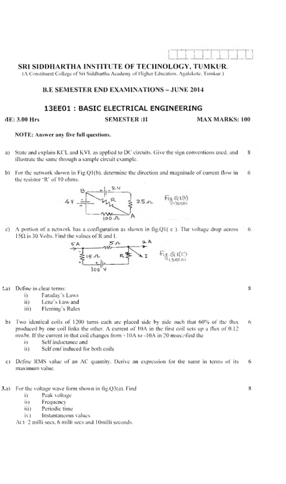
SRI S1DDHARTHA INSTITUTE OF TECHNOLOGY, TUMKUR. (A Constituent College o f Sri Siddhartha A c ad emy o f Higher Education, Agalakote, Tumkur .) B.E SE M E ST E R END EX A M IN A TIO N S - JUN E 2014 13EE01 : BASIC ELECTRICAL ENGINEERING dE: 3.00 Hrs SEMESTER :1I MAX MARKS: 100 NOTE: Answer any five full questions. .a) State and explain KCL and KVF as applied to DC circuits. (}ive the sign conventions used, and illustrate the same through a sample circuit example. b) For the network shown in Fig.Q l(b), determine the direction and m agnitude o f current now in the resistor Ml' of 10 ohms. e) A portion of a network has a configuration as shown in fig .Q l( c ). The voltage drop across 15Q is 30 Volts. Find the values o f R and I. 5~/\ .fT-TL r 3 -A - \ i i£ C .O \ !.a) Define in clear terms: i) Faraday's Laws ii) Lenz's Law and iii) Flem ing's Rules 8 b) Two identical coils o f 1200 turns each are placed side by side such that 60% o f the (lux produced by one coil links the other. A current o f 10A in the first coil sets up a flux o f 0.12 mvvbr. If the current in that coil changes from -t 10A to -10A in 20 msec,’ find the i) Self inductance and ii) S elf em f induced for both coils 6 c) Define RMS value o f an AC quantity. Derive an expression for the same in terms o f its maximum value. 6 For the voltage wave form shown in fig.Q3(a). Find i) Peak voltage ii) Frequency iii) Periodic time iv) Instantaneous values At t-'2 mil 1i secs, 6 milli secs and 10miIii seconds. 8 3.a) \3>eeo\ b) Define i) ii) Form factor and peak factor and find their value for a sinusoidally varying current. Power factor and give its value for a pure R, Pure L and Pure C circuit. c) A resistor R is connected in series with the capacitor 4C ’ to a 501 Iz, 240V supply. Find the values o f R and C. so that R absorbs 300W at lOOVolts. 4.a) In a balanced 3 phase, inductive load, the resistance measured between any twro term inals is 3 ohms, if the supply voltage is 415 volts and line current is 100A. Find the im pedance per phase o f the load and its power factor when it is connected in (i) Star (ii) Delta. 8 b) With the help o f neat diagram, explain the construction o f a dynam ometer type wattmeter. 6 c) Write briefly on i) Need for Earthing ii) Electric shock and precautions against the same. 6 5.a) With the help o f a neat diagram, explain the construction and w orking principle o f a single phase induction type energy meter. 10 b) W ith a neat sketch, with parts named, explain the working principle o f a DC generator. Hence derive the expression for the induced em f in the machine. 10 6.a) W rite a note on ( i) N ecessity o f starter in DC motors ii) A pplications o f DC motors 6 b) Define torque and obtain an equation for the torque developed by a DC motor. 6 c) A 4 pole DC shunt m otor takes 22.5A from a 250V supply. The armature resistance is 0.5H and shunt field resistance is 125 Q. The armature is wave wound with 30 slots and 10 conductors per slot. If flux per pole is 20 mwb, calculate: i) Speed ii) Torque developed and iii) Power developed 8 7.a) W hat are the main parts o f a Transformer? W hat is the function and the main material used for construction in each case? 6 b) W hat are salient and non salient synchronous machines? Derive the em f equation o f a synchronous generator. 6 c) A 24 pole turbo alternator has a star connected armature winding with 144 slots. 10 conductors per slot. It is driven by a low speed Kaplan turbine at a speed o f 250 rpm. The winding factors are kp= l and k<j=0.966. The flux per pole is 67.3 mwb. Calculate i) The frequency and m agnitude o f the line voltage, ii) The output RVA o f the machine, if the total current in each phase is 50A. 8 The maximum efficiency at full load, upf o f a single-phase, 25 M VA, dOO/IOOOV, 50hz, transform er is 98%. Determ ine its efficiency at: i) 75% load, 0.9 PF and ii) 50% load, 0.8 PF 6 The rotor induced voltage o f 3-phase, 4 pole induction motor fed by an alternator is observed to make 1.5 alternations per second. The star connected alternator has 592 full-pitched armature conductors in series per phase with K<j=0.966. The line voltage o f 6.6 kV is developed when the flux per pole is 60 mwb. Determ ine the speed o f the induction motor. 8 Define i) Rotating magnetic field ii) Synchronous speed iii) Slip and iv) Slip speed W ith reference to a 3 phase induction motor. 6 Com m on for: All branches ++111101111++
