Jump to report - sae india uvce
advertisement
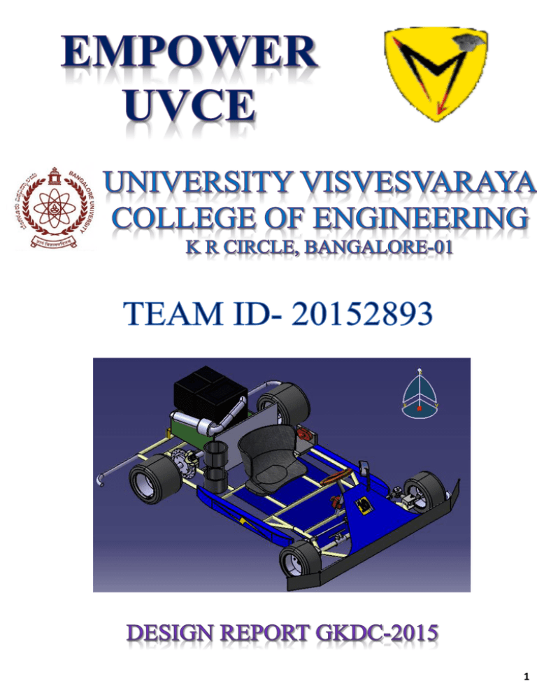
1 Contents 1. Introduction 3 2. Chassis 3 3. Tyres 7 4. Engine and Powertrain 8 5. Steering 10 6. Brakes 14 7. Conclusion 15 2 ABSTRACT – To design and build a go-kart completely designed by students within a budget of Rs.80000/-. To compete in national level GoKarting Championship ISNEE GKDC-2015. The design is optimised considering performance, economy, availability and budget. INTRODUCTION CHASSIS The design process started of keeping the ergonomics and safety of the driver in mind and of top priority by taking measurements with the driver being seated. A prototype of 1:1 dimension was made to finalize the design. Suitable measurements for engine were taken as per the given specifications and a 2-D sketch of the model was prepared and chassis model was done using Catia wireframe design. Transmission was decided based on the power output of the engine provided. The steering considerations were made by doing a thorough market research on various gokarts available and improvising on it based on our conceptual knowledge, similarly brakes were designed. The design is optimized and the whole assembly was envisioned to provide safety and efficiency of the vehicle thus ensuring our Go-kart is reliable. INTRODUCTION Design Considerations: We have used Ladder frame which is of convectional type. Chassis is designed according to the rules mentioned below; The chassis for Go-kart Design Challenge has been designed strictly adhering to the parameters given in rulebook. Types of Chassis 1. 2. 3. 4. 5. Back bone chassis Ladder Frame chassis Tubular Space frame Monocoque Ultra-Light Steel Auto Body Types of Frames 1. Convectional frame 2. Integral frame 3. Semi-Integral Frame CHASSIS WITH DIMENSIONS SHOWN 3 Sr.no 1 2 3 4 5 6 7 8 RULES Four wheeled vehicle. Wheel base: 1066.8-1397 mm Front track width should be 80% of wheel base. Minimum clearance of 3 inches should be present between driver and any component of vehicle in static and component of vehicle in static and dynamic conditions. Material- seamless pipes with minimum crosssection of 1 inch. Ground clearanceminimum of 1 inch should be maintained. Jack point and toe point- 2 jack points and toe points, one in front and one in rear painted in orange for easy visibility. Bumpers must be installed in front and back made up of seamless tubes with a minimum cross-section of 1 inch Implemented Yes Yes Wb=1168.4mm Tw=965.2 mm Yes • • • • Roll Cage/Roll Bar is not necessary since the chances of rolling is almost negligible due to lower Center of Gravity (Cog) Wheel base and Track width have been chosen accordingly to suit the other design parameter considerations like lower turning radius, weight and performance. Ground clearance is taken as 2.54cm (1 inch) for better road grip. Composition of the Material Used: Yes Yes Yes Yes CONSIDERATIONS: We have used seamless tubes for the design of the go-kart model. After much research and strict reasoning we found EN8 material Alloy Steel (equivalent to 45C8 Steel) was best for our chassis material. As we researched we found out the following properties: Chemical Element Percentage Carbon 0.16-0.18 % Sulphur 0.040 % max Phosphorous 0.040 % max Manganese 0.70-0.90 % max Silicon 0.040 % max Properties of the material: Max stress Yield Stress 0.2 % Proof Stress Elongation Hardness density 700-850 n/mm2 465 n/mm2 Min 450 n/mm2 Min 16% Min 201-255 Brinell 7.95 g/cc Track width=965.2 mm Wheel base=1168.4 mm Weight of all the components These are the following reasons for the above considerations: • Circular beam is selected because they have better stiffness value than Rectangular beam of same parameters and also for the same stiffness the Circular beam weighs less than the Rectangular beam. 4 COMPONENT WEIG HT (kg) Unsprung masses Driver Engine Chassis Sprocket Fuel tank Brake Fire extinguisher 55 15 20 1 3 4 2 Steering rod and linkages Total Sprung masses Front kingpin(right) Front kingpin left Rear bearing (right ) Rear bearing(left) Rear shaft Tires Total NET WEIGHT 5 Calculation of Centre of gravity: The formula for calculating cog is derived from the below figure 107 1 1 1 1 7 20 31 140 DESIGN PROCEDURE Calculation of longitudinal loading- transfer of weight from front to back wheel. 𝑑𝑣 𝑅𝑓 = 𝑀𝑔 𝑙 − 𝑎 − 𝑀ℎ( 𝑑𝑡 )/l Where, l=wheel base M= mass g=acceleration due to gravity h=height of cog from the ground a=length between driver and front axle 𝑑𝑣 ( 𝑑𝑡 ) = acceleration of the vehicle 𝑅𝑓 = 378.54 N Therefore the net reaction acting on a rear wheel = 38.5 kg. Wheels Reaction (kg) Front left 21.5 Front right 21.5 Rear left 38.5 Rear right 38.5 Thus our chassis has a weight distribution of 35% front and 65% rear which is 80% of weight distribution seen in optimum chassis. Using this data we move towards the calculation of cog. 𝑊𝐹 ∗𝑙 𝑊 𝑊2 y= 𝑊 𝑡𝐹 b= −𝑑 − 𝑊1 𝑊 ∗ 𝑑 + 𝑊4 𝑡 𝑊 𝑅 where, 𝑊1 & 𝑊2 = Force acting on the front tires 𝑊3 & 𝑊4 = Force acting on the rear tires 𝑊 = Net force of the chassis b= cog from rear axle y= cog from the 𝑥1 -𝑥1 So we get b=682.98 mm Y=381mm Z=196.85 mm Selection of the Track Width: We chose the wheelbase of 1168.4 mm because of the following reasons • Smaller track width (Front track) should be 80% of the wheelbase, larger the wheelbase larger is the front track width. • With this wheelbase, all the components could be arranged accordingly • As wheel base is kept as minimum as possible critical turning radius decreases and at same time critical turning speed increases Rear track width is set to 1066.8 mm. The reason for this is: 𝑉 2 ∗ 2ℎ = 𝑔 ∗ 𝑡 ∗ 𝑅 Where, V=velocity in m/s=7.97 m/s h=cog in z axis=196.85 mm R=turning radius=2.4 m t=rear track width=1066.8 mm 5 WELD STRENGTH Calculated welding strength for the standard material with circular cross section was calculated as 143 N/mm2 for a load of 1000 N applied on it this is stress created so it is less than the material stress that is 465 N/mm2. Even the chassis is designed to take good amount of static and dynamic load. The impact force is calculated using the formula, 1 K.E=2 𝑚𝑉 2 = 𝐹 ∗ 𝑑 m=Total mass of the vehicle=140 kg V=Velocity of the vehicle=11.11 m/s d=Displacement of the vehicle=1 m F=Impact force=8.64 KN But, for the safety of the driver we have done the analysis of the go-kart taking the impact force to be 20 KN. FRAME ANALYSIS: FACTOR OF SAFETY The different views of the go-kart are shown below Front impact – Force = 21000N Max FOS = 15 TOP VIEW OF THE GO-KART MODEL Side impact = 21000N Max FOS = 15 FRONT VIEW OF THE GO-KART MODEL Rear impact = 21000N Max FOS = 15 SIDE VIEW OF THE GO KART MODEL 6 DEFORMATION Front impact – Force = 21000N Max deformation seen = 3.28mm TYRES • Tread less tyres provide largest possible contact patch to road and maximise traction. • Steering and braking require maximum traction from each wheel. • Since there is no tread pattern, slick tyres don’t deform much under load. The reduced deformation allows the tyre to be constructed of softer compounds without excessive overheating and blistering. • They offer better grip with low friction. Side impact = 21000N Max deformation seen = 3.23mm STRESS ACTING WHEEL RIM USED IN OUR GO-KART Force applied = 21000N Side impact = 21000N 7 ENGINE AND POWERTRAIN INTRODUCTION Construction of Shear Force and Bending Moment diagrams The net weight acting on the vehicle is shown below The power train of go-kart consists of a Briggs and Stratton 550 series engine, whose power is transmitted through a chain drive mechanism. The engine will be provided by ISNEE. The engine position is longitudinal with respect to the go-kart chassis, and is in-line with the central axis of the chassis. A stock exhaust is being used as the exhaust for the go-kart. The rear axle is made of C40 steel. Its diameter is 27mm and length is 1066.8mm. Bearings used are SKF roller bearing RNU 204 We are using a chain transmission with a pitch of 9.525mm. Given below are the calculation of the rear axle, sprocket and ball bearings. Taking moment about R 0= (-140*381) + (W (front)*1168.4) W (front) = (140*381)/1168.4 W (front) =45.532kg W (rear) =140-45.532 =94.468kg Total weight acting on the rear axle is 94.468kg. The total load distributed to each bearing is 47.234kg. WC=47.234kg WD=47.234kg REAR AXLE CALCULATIONS: Total length of the Rear Axle=L=1066.8mm Bearing point location should be within 0.557L, according to airy point’s concept, if concentrated loads occur on points separated by 0.557L where L is the length of the beam, then it has least bending moment. The distance between the bearings is 498 mm, which lies within the range. 498/2 = 249mm. The bearing points are 249 mm away from the Centre of the rear axle on either side. Consider section AC: Force= RA=47.234kg*9.81=463.365N Moment at a point X=M=463.365*X N-mm At X=0mm, M=0 N-mm At X=274mm, M=463.365*274 =136229.468 N-mm Consider section CD: Force= RA +WC = (47.234*9.81)-(47.234*9.81) =0 N Moment at a point X=M = (463.365*X) + (-463.365*(X-274)) =463.365*274 =136229.468 N-mm (Moment is constant) Consider section DB: Force= RA + WC + WB = 463.365-463.365463.365 =-463.365 N Moment at a point X=M = 463.365X + (-463.365*(X-274)) + (-463.365*(X-(274+562.8))) 8 = 499614.44-463.365X At X=274+518=792mm, M=136229.468N-mm At X=1066.8mm, M=0 N-mm Shear Force and Bending Moment Diagrams: REACTION DIAGRAM: 27= ((16/πτed) ((2*136229.468)2 + (1.5*57777)2)1/2)1/3 Τed= ((16/π*273) ((2*136229.468)2 + (1.5*57777)2)1/2) Τed = 73.97 MPa Note: For C40 steel, maximum allowable shear stress is 328.6 MPa. Factor of safety= 328.6/73.97 =4.44 SHEAR FORCE DIAGRAM: BENDING MOMENT DIAGRAM: Power transmission calculations The maximum speed of the engine is 3600 RPM The pitch of the sprocket and chain setup is given by P<=0.25(900/n1)2/3 P<=0.25(900/3600)2/3 P<=9.92 mm We have standard pitch as 9.525 mm In order to have a top speed of 60 km/h we must have the speed of the driven sprocket as 1224.889 rpm. We have the formula N1/N2 = Z2/Z1 Where, N1=speed of the driving sprocket N2=speed of the driven sprocket Z1=Number of teeth on driving sprocket. Z2=Number of teeth on driven sprocket. Therefore (3600/1224.889) = 2.93~3.00 Calculation of maximum shear Stress Induced A safe diameter can be calculated using the formula based on (1)Maximum Shear Stress Theory The diameter of shaft will be D=27mm We have the formula as D= ((16/πτed) ((KbMb) 2 + (KtMt) 2)1/2)1/3 Kb=2, Kt=1.5, Mb=136229.468 N-mm, Mt=57777N-mm We have stock sprockets number of teeth as Z1=14 Z2= 3.00*14 = 42 = 42 teeth. We have got the diameter of driving sprocket as D1 = P/ sin (180/Z1 ) D1 = 4.29 cm Diameter of driven sprocket is D1= P / sin (180/Z2) D2 = 12.75 cm 9 Bearing design As it’s clear the radial load is the resultant load of braking and weight of the vehicle on bearing. The net Radial load on the Bearing is WR= 812.40 N When it comes to axial load, it is considered only when the vehicle takes a turn as the centrifugal force acts on the vehicle. Here we considered the centrifugal force as the axial load on axles of the vehicle Let us consider vehicle moving with velocity V=60 Km/hr. and taking turn of radius R=14 m. Then the centrifugal Force on the vehicle = (MV2)/R =140*(60*5/18)2/14 Centrifugal force =2777.77 N Taking moment about R 0=1168*W (front) – 371.557*2777.77 W (front) = 906.082 N W (rear) = 1894.075 N Therefore the total axial load on Rear Axle is WA=1871.665 N Axial Force on each Bearing is = 935.833 N. The output speed of the Engine is n=1224.889rpm. Let the life of Bearing is 8hrs / day Then Life of the Bearing in revolutions=60*n*life =60*1224.889*365*5 =134.125*106mor. Now the total Load on the bearing is given by P=XVWR+YWA Now to find the values of X and Y From the data hand book, for d=27mm, co=7350 N (WA/WR) = (935.833/ 812.40) = 1.166 (WA/CO) = (935.833 / 7350) = 0.1288 From DDHB For WA/C0=0.1288, X=0.56, V=1 Y=1.454 Equivalent Load due to dynamic loading P = X*V*WR + Y*WA = (0.56*1*812.40) + (1.454*935.833) = 1815.645 N LIFE OF THE BEARING L = (C/P) 10/3 L = (14700/1815.645)10/3 1065.66 Million L>LREQUIRED Therefore the bearing selected is suitable. The bearing is SKF roller bearing RNU 204. The view of the roller bearing designed STEERING INTRODUCTION The main aim is to design an optimized steering mechanism for a wheel base of 1168.4mm and front track width of 965.2mm with positive stops. CONSIDRATIONS AND REASONING (1) Steering Mechanism Ackerman mechanism: Ackermann steering mechanism is a geometric arrangement of linkages in the steering of a car or other vehicle designed to solve the problem of wheels on the inside and outside of a turn 10 needing to trace out circles of different radius. The intention of Ackermann geometry is to avoid the need for tyros to slip sideways when following the path around a curve. The geometrical solution to this is for all wheels to have their axles arranged as radii of a circle with a common Centre point. As the rear wheels are fixed, this Centre point must be on a line extended from the rear axle. Intersecting the axes of the front wheels on this line as well requires that the inside front wheel is turned, when steering, through a greater angle than the outside wheel. i) Linkage Mechanisms Direct Linkage: Generally direct linkage mechanism are simple enough to build, easy to handle, can be assembled and disassembled easily, cheap, lightweight, can be made according to the Ackerman Principle& desired steering ratios can be maintained when compared to rack and pinion mechanism. Rack and pinion type of mechanism is not cost effective, assembly & disassembly of the same is complex, heavier, modifying the steering ratios for go kart handling is risky. PARTS USED The following parts were used in the design of our steering assembly: Steering Column (1 no): It is a device intended Primarily for connecting the steering wheel to the steering mechanism or transferring the driver's input torque from the steering wheel. Axle (1-nos) with C- Brackets (2-nos): The main function of the axle is to provide the support to steering column and to house the ball bearing. This is attached on the chassis and the two CBrackets house the king pins and facilitates their movement. Triangle Arm (1 no.): This arm is designed to convert the rotary motion of steering column to the reciprocating motion of the tie rods. It is fit perpendicular to the steering column. Ball bearing (1 no): It is a type of rolling-element bearing that uses balls to maintain the separation between the bearing races. In our design, it is used at the end of the steering column to facilitate the swiveling of the steering column. Tie rods (2 no’s): A tie rod is a slender structural unit used as tie and (in most applications) capable of carrying tensile loads only. In steering mechanism, they differ from the archetypal tie rod by both pushing and pulling (operating in both tension and compression). Kingpins (2 no’s): It is the main pivot in the steering mechanism. It is usually supported in bronze bushings. They are normally a press fit in their housings, which means that they have to be reamed to size. Rod Ends M20 (7 no’s): These acts as the main connectors between two rigid rod linkages. They come in positive or negative types. In our case we use negative rod ends with M20 thread specifications to attach the tie rods to the king pins and to the swiveling arm. APPROXIMATIONS: The following approximations have been considered: Caster Angle: Positive caster angle of 6 degrees has been given to ensure feedback from the tyre to the steering wheel. This angle was approximated, keeping in mind the tire force. Camber Angle: Since camber angle depends on the temperature profile of the tire, it cannot be calculated on paper. Therefore, a negative camber angle of 3 degrees has been approximated. Toe in/Toe out: Since the vehicle speed is limited to 40kmph, toe in/toe out is not necessary because it contributes to tire wear. Tire Sensitivity: The tire Stiffness is approximately taken a 55000 N/rad and 60000 N/rad for the front and rear tires respectively. FINAL ASSEMBLY OF STEERING CALCULATIONS Steering arm length: Steering wheel height=330mm Steering wheel horizontal distance from front axle=127mm Therefore by Pythagoras theorem, Steering arm Length=353.59mm and Steering arm 0 inclination=52 11 Ackerman angle: Wheel base=1168.4mm Front Track Width=965.2mm Therefore, front axle length=600mm. Distance between kingpins=711.2mm Therefore, distance from central axis to each kingpin=355.6mm Using Pythagoras theorem, Ackerman angle=160 Ackerman angle estimation using CATIA v5 Maximum Velocity of Turning When a vehicle takes a turn, the centrifugal force tries to push out the vehicle; it acts along the cg and while self-weight tries to bring it down, acting along CG as well. The condition for topple occurs when the road reaction on the inner wheel gets 0 or negative. This could be the limit for the speed at turn, so the maximum centrifugal force is limited by toppling condition. Taking Moments about the outer wheel's contact with the ground we get. 𝐹𝑐𝑒𝑛𝑡 * h – w *b + 𝑅1 * 2b = 0 Taking R1 = 0 to analyze the critical case, and substituting values of forces (𝑚𝑣 2 /r) *h = mg * b v= √ (b*g*r/h) Height of cg= 0.19685m, half of track width=965.2/2= 482.6mm and at turning radius= 2.4m, v = √ (0.4826*9.8*2.4/ 0.19685) = 7.593m/s = 27.33 km/h Maximum lateral acceleration = v²/r = 7.593²/2.4 = 24.022m/s² Position of cog of the vehicle from rear axle = lr = 682.98mm Slip Angle: During turning centrifugal force acts outwards, it is resisted by the lateral tire forces acting inwards on the tire contact patches on front and rear, we consider the simplified bicycle model with two wheels to analyze this. Linearity is assumed between tire lateral force and tire slip angle. Ca=Fa/α,Ca is tire stiffness constant M = 140 kg; lr=682.98mm; lf=485.42mm; l=1168.4mm; Caf = 55000N / rad; Car = 60000N /rad; Calculating slip angles Taking Moments about front tires Car * αr * l = (m* v² * lf) / r αr = (m* v² * lf) / (r * l *Car) 140∗7.5932 ∗0.48542 = 1.1684∗60000∗2.4 ; ∝𝑟 = 0.02328 𝑟𝑎𝑑 Taking Moments about rear tires Caf * αf * l = (m* v² * lr) / r αf = (m* v² * lr ) / (r * l *Caf) 140∗7.5932 ∗0.68298 = 1.1684∗55000∗2.4 ; ∝𝑓 =0.03574 rad For steady state αr = β+ (lr /r) 0.02328= β+ (682.98/ 2400) = > β= -0.2613 rad = -14.97° αf = δ+ β- (lf/ r) 0.03574 = δ – 0.2613- (485.42 / 2400) = δ = 0.4992 rad = 28.607 ° Tyre forces Flf = Caf * ∝𝑓 = 55000*0.03574 = 1965.7 N Flr = Car * ∝𝑟 = 60000*0.02328 = 1396.8 N 12 FORCES ON THE KINGPIN STUB The king pin stub suffers higher bending moment due to lateral tire forces trying to bend it towards the instantaneous center. The Right king pin being the outer kingpin (while taking a left turn) will suffer a higher stress since mass transfer happens towards right. Also traction is higher on the right. The kingpin stub can be considered as a separate entity to draw a free body diagram The lateral force on the outer tire can be taken as 0.5 of total front lateral force Fl = 1965.7 / 2 = 982.85 N As shown in the drawing Flateral = Fcentrifugalfront = 982.85 N and front right reaction Rf= w (weight of vehicle acting on the front right) = m*g * lr /l = 140*9.8 * 682.98 / 1168.4 = 801.992 N Steering Forces: The steering wheel effort is given in the following graph which relates to the lateral acceleration. Lateral acceleration, ay = 24.022 m/s² = 2.45 g from graph Msw = 3 ft. lb. = 8.96 N m Steering Mechanism showing double 4 bar chain and length of tie rods and kingpin link The steering wheel torque and torque required at king pin King pin link= 120mm tie rod = 320mm welded link connected to steering wheel= 80mm distance between two king pin axles= 711.2 mm steering wheel torque= 8.96Nm Torque required at king pin= 16.361 Nm The forces are then applied in the Inventor model to carry out the dynamic analysis of steering to check for the safe stress on the king pin and tie rods. Steering Ratio is considered 1:4 where 1 degree of change in wheel angle is due to 4 degrees of change in steering wheel angle. Ackerman’s Ratio & Turning Radius Track width = 38” Wheel base = 46” w/l=38”/46”=0.826 By trial and error method, we consider δi=32o From the below figure Turning radius, Ri= δi+w/2 δo=Cot -1 (w/l + Cot δi) R=√ (a2 +l2 Cot2δ) where δ=Cot-1 ((Cot δ0 + Cot δi)/2) we get, δo= 22.398 and there by turning radius is calculated as follows In meters, Ri = (1.1684)*Cot (32o) + (0.9652)/2 , Ri= 2.3524 m From the turning radius formula, R = 2.4 m 13 BRAKES Turning radius of the four wheeler 22.398o 32o R o R C i R Hence, for δi=32o & δo =22.398o When plotted δo vs δi δ =Cot -1 ((Cot δo +Cot δi)/2) δ=26.412o Turning radius R=2.4m From the above graph Ackerman ratio is 0.823 Therefore, verified. 0.826 ≈ 0.823 β or Ackerman angle Calculation 38” 28” β By trial & error method : (w – 2d sinβ)=(w – dsin (β +δi) + d sin ( β-δo))2 + (d cos ( β+δo) – d cos( β+δi))2 From (Book) calculations by trial & error method least error of 1% is obtained for β=16o Brake chosen for go-kart: Discover 125 st-front disc brake. Type of disc: Petal disc. Main reasons for choosing petal disc brake: Optimum disc diameter and it satisfies our need. Proper heat dissipation i.e., better than the conventional round disc. Disadvantages of using petal disc: Surface area is reduced by 20% due to which the friction area is lesser and hence the efficiency reduces by a certain amount. Since surface is uneven on the outer diameter, a chain saw effect is produced on the brake pad, this is like shaving off the brake layer each time you apply the brake, so eventually the brake pads will be worn off. However, this occurs only after considerable usage and need not be worried about brake wear. Estimated cost: ₹4000/Disc diameter: 200mm Location of disc on the rear axle: 38mm from the right bearing. Length of cable/tube required: 1250mm caliper specifications depend on the disc as we will get specific calipers for a particular set of disc. Pedal travel: 20mm CALCULATIONS: Maximum speed of go-kart= 40km/h =11.11m/s Desired braking time = 3.5 s Deceleration = maximum speed braking time = 11.111/3.5 =3.1746m/s2 Braking force = BF = mass*deceleration = 140*3.1746 = 444.44kN Braking torque = Tb Tb= BF* tire radius tire to brake speed ratio = 444.44*130*10-3/1 = 57.7772 Nm 14 Disc effective radius = (Din + Dout)/4 = (170+200)*10-3/4 = 92.5*10-3m Theoretical clamp force = CFa CFa = Tb / (re*μf*n) =57.7772/ (92.5*10-3*0.35*2) = 892.312 N Master cylinder area =A A = (π/4)*(12.5*10-3)2 = 1.227*10-4 m2 Caliper base area = (π/4)*(25*10-4)2 = 4.91*10-4 m2 DISC BRAKE WITH CALIPER REFERENCES Actual clamp force = CFa calliper base area CFa = BF*2* Master cylinder area = 444.44*2*4.91/1.227 = 3556.969 N Braking pressure = P P = CFa / Caliper base area = 3556.969 / (4.91*10-4) =7244.336kN/m2 Average deceleration of entire stop = max speed (max/deceleration + 0.3g) R.S Khurmi “A text book of machine design” Rajesh Rajaman “Vehicle Dynamics and Control” Thomas.D.Gillespies “Fundamentals of vehicle dynamics” G.B,S Narang “ Automobile Engineering” J.B.K Das and P.L Srinivasmurthy “ Design of machine elements” R.S Khurmi “A text book of machine design” K Lingaiah “Design data hand book" SKF online bearing calculator AutomotiveTransmissions Gisbert Lecher CONCLUSION = 11.111 (11.111/3.1764 + 0.3∗9.81) = -1.7245m/s2 Stopping distance = S (max speed)^2 S = 2g∗average deceleration = (11.111)2 / (2*9.81*1.7425) = 3.6487m BRAKE PEDAL DESIGN After finishing the designing of the Go kart project we conclude that the Designing process in theory might look Intuitive and Exciting as it is but it as much equally requires Structured Planning, Movement & Brainstorming. A lot of in depth understanding of concepts is needed and one should also be exposed to Industry Design Practices and Standards. There should be a sense of responsibility in choosing parts considering safety. We were flooded with ideas and concepts, but it took us in depth knowledge & understanding to settle on best design. Market Availability & Innovative ideas were cleverly matched up to get the best of both the worlds. This is the dream of our team eMpower UVCE. We at eMpower UVCE are envisioned to empower the automobile industry and the world at large to create better citizens for the future and help and empower the humanity! 15
